Positioning method based on laser radar and IMU tight coupling

A lidar and tightly coupled technology, applied in surveying and navigation, reradiation of electromagnetic waves, measurement devices, etc., can solve problems such as large amount of calculation and failure of point cloud matching

Active Publication Date: 2020-07-03
ZHEJIANG UNIV
View PDF7 Cites 10 Cited by
  • Summary
  • Abstract
  • Description
  • Claims
  • Application Information

AI Technical Summary

Problems solved by technology

This patented technology makes up for the situation that the camera is prone to positioning failure when the illumination changes are sensitive to a certain extent. However, when the image feature tracking fails, the

Method used


Image

  • Positioning method based on laser radar and IMU tight coupling
  • Positioning method based on laser radar and IMU tight coupling
  • Positioning method based on laser radar and IMU tight coupling

Examples


Embodiment Construction

[0033] In order to describe the present invention more specifically, the technical solutions of the present invention will be described in detail below in conjunction with the accompanying drawings and specific embodiments.

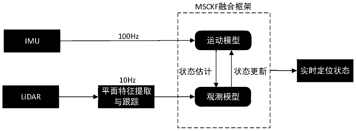
[0034] Such as figure 1 As shown, the present invention is based on the robot localization method of lidar and IMU tight coupling, comprises the following steps:

[0035] S1. Read the output data of the IMU, and estimate the real-time motion state of the system through the motion model.

[0036] The motion state of the system includes at least the robot's position, orientation, and speed information, and maintains a fixed-size sliding window about the lidar pose. The sliding window stores the latest m laser radar positions, orientations, and other information in the robot's trajectory. . The IMU outputs acceleration and angular velocity data at a frequency of 100 Hz, estimates the motion state of the system according to the motion model of the IMU, and ...


PUM


Abstract

The invention discloses a robot positioning method based on laser radar and IMU tight coupling, and the method comprises the steps: estimating the real-time motion state of a system through an IMU, extracting plane features for tracking through the point cloud data of the laser radar, and correcting the motion state estimated by the IMU through an observation model of the plane features. Accordingto the method of the invention, the MSCKF framework is utilized to realize advantage complementation of the laser radar sensor and the IMU sensor. On one hand, IMU high-frequency motion estimation can estimate the real-time state of the system, and on the other hand, the plane features extracted by the laser radar point cloud can be tracked in the environment in a robust manner, so that the system state can be corrected regularly, and the robustness and accuracy of positioning are maintained while the calculation complexity is reduced.

Description

technical field [0001] The invention belongs to the technical field of robot positioning, and in particular relates to a robot positioning method based on tightly coupled laser radar and IMU. Background technique [0002] Autonomous navigation is a key technology for the automatic operation of mobile robots. At present, the most mainstream navigation technology is SLAM, which means "instant positioning and map construction" in Chinese. Its principle is to scan the surrounding environment through sensors, and then construct a and Maps that are consistent with the real environment, at the same time locate the position of the robot, and plan a correct path, and finally guide the robot to reach the designated destination safely. [0003] Positioning technology is the supporting technology to realize the robot's autonomous navigation. Whether the positioning is accurate determines whether the robot can accurately and efficiently complete functions such as higher-level planning an...

Claims


Application Information

Patent Timeline
IPC IPC(8): G01C21/16G01S17/02G01S17/87
CPCG01C21/165G01S17/87
Inventor 吕攀张恒杨国青李红潘之杰吴朝晖
Owner ZHEJIANG UNIV
Why Eureka
Try Eureka