Mr imaging with motion detection

a technology of magnetic resonance and motion detection, applied in the field of magnetic resonance (mr) imaging, can solve the problems of motion artifacts in the reconstructed mr image, adversely affecting image quality, blurring, misregistration, etc., and achieves the effect of reducing image artifacts, avoiding image artifacts, and effective and targeted reduction of motion-induced image artifacts

Active Publication Date: 2018-07-26
KONINKLJIJKE PHILIPS NV
View PDF10 Cites 4 Cited by
  • Summary
  • Abstract
  • Description
  • Claims
  • Application Information

AI Technical Summary

Benefits of technology

[0025]In a preferred embodiment of the invention, a motion-compensated MR image is reconstructed from the fully sampled set of k-space profiles, wherein the subsets are weighted according to the detected motion. The subsets are combined into the fully sampled set of k-space profiles by weighted superposition. The weighted superposition enables an effective and targeted reduction of motion-induced image artifacts in the reconstructed MR image. The weighting factors of the weighted superposition are derived from the comparison of the gradient MR images so that image artifacts are avoided by applying a reduced weighting to the motion-corrupted subsets.
[0026]In an alternative embodiment, motion correction may be applied to at least one of the subsets according to the detected motion such that a motion-corrected MR image can be reconstructed from the fully sampled set of k-space profiles formed from the motion-corrected subsets. As in conventional PROPELLER imaging, the method of the invention may comprise the step of estimating and correcting motion-induced displacements and phase errors in the subsets. For example, displacements (translation and / or rotation) and phase errors, which are caused by patient motion, can be derived from the comparison of the gradient MR images. These factors may be corrected for in each subset in accordance with the invention prior to reconstructing the motion-corrected MR image. The invention thus provides a MR imaging method that is robust with respect to motion of the examined patient during MR signal acquisition.
[0027]According to another alternative, one or more motion-corrupted subsets are re-acquired, such that a final MR image is reconstructed from the fully sampled set of k-space profiles formed from the not motion-corrupted subsets and the re-acquired subsets. Motion-corrupted subsets are identified by the comparison of the gradient MR images. The respective subsets are then re-acquired. Optionally, the FOV of the k-space sampling is adapted in the step of re-acquiring the subsets according to the detected motion. In this way, the FOV may follow the detected motion of the imaged object.

Problems solved by technology

In a variety of MRI applications, motion of the examined patient can adversely affect image quality.
Motion of the patient during that finite acquisition time typically results in motion artifacts in the reconstructed MR image.
In the case of medical MR imaging, motion artifacts can result for example from cardiac and respiratory cyclic motion, and other physiological processes, as well as from patient motion resulting in blurring, misregistration, deformation and ghosting artifacts.
However, drawbacks of the known PROPELLER approach result from the fact that its application is restricted to the specific circular acquisition of k-space profiles from a number of successively rotated blades.
The highly effective motion-compensation and motion-correction concept of the PROPELLER approach is not compatible with Cartesian k-space sampling schemes.
However, a drawback of the navigator technique is that additional acquisition of the navigator signals is required which results in an extension of the overall scan time.
Moreover, the known navigator methods are difficult to apply if the volume of interest, from which the MR signals for imaging are to be acquired, partially overlaps with the navigator volume.
If the navigator volume is (at least partly) superimposed upon the respective volume of interest, the image quality may be degraded due to incorrect detection of the motion state or due to saturation of the nuclear magnetization within the navigator volume.

Method used


Image

  • Mr imaging with motion detection
  • Mr imaging with motion detection
  • Mr imaging with motion detection

Examples


Embodiment Construction

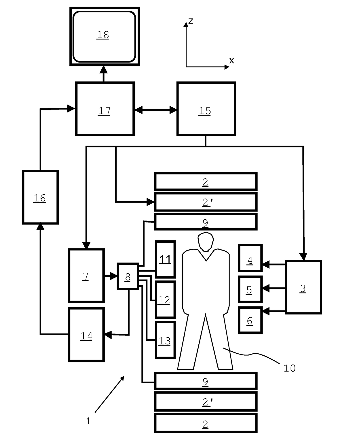
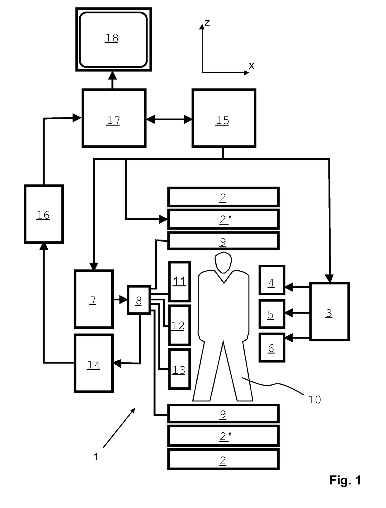
[0038]With reference to FIG. 1, a MR device 1 is shown. The device comprises superconducting or resistive main magnet coils 2 such that a substantially uniform, temporally constant main magnetic field B0 is created along a z-axis through an examination volume. The device further comprises a set of (1st, 2nd, and—where applicable—3rd order) shimming coils 2′, wherein the current flow through the individual shimming coils of the set 2′ is controllable for the purpose of minimizing B0 deviations within the examination volume.

[0039]A magnetic resonance generation and manipulation system applies a series of RF pulses and switched magnetic field gradients to invert or excite nuclear magnetic spins, induce magnetic resonance, refocus magnetic resonance, manipulate magnetic resonance, spatially and otherwise encode the magnetic resonance, saturate spins, and the like to perform MR imaging.

[0040]More specifically, a gradient amplifier 3 applies current pulses or waveforms to selected ones of...


PUM


Abstract

The invention relates to a method of MR imaging of an object (10) placed in the examination volume of a MR device (1). It is an object of the invention to provide a method that enables efficient motion-compensation and/or motion-correction and that is compatible with Cartesian sampling of k-space. The method of the invention comprises: —generating MR signals by subjecting the object (10) to a MR imaging sequence of at least one RF pulse and switched magnetic field gradients; —acquiring the MR signals as a plurality of temporally successive subsets, each subset comprising a number of k-space profiles with sub-sampling of k-space, wherein the subsets complement each other to form a fully sampled set of k-space profiles; —reconstructing a single-subset MR image from each subset; —computing a gradient MR image from each single-subset MR image; and —detecting motion by comparing the gradient MR images with each other. Moreover, the invention relates to a MR device (1) and to a computer program for a MR device (1).

Description

FIELD OF THE INVENTION[0001]The invention relates to the field of magnetic resonance (MR) imaging. It concerns a method of MR imaging of an object placed in the examination volume of a MR device. The invention also relates to a MR device and to a computer program to be run on a MR device.BACKGROUND OF THE INVENTION[0002]Image-forming MR methods which utilize the interaction between magnetic fields and nuclear spins in order to form two-dimensional or three-dimensional images are widely used nowadays, notably in the field of medical diagnostics, because for the imaging of soft tissue they are superior to other imaging methods in many respects, do not require ionizing radiation and are usually not invasive.[0003]According to the MR method in general, the body of the patient to be examined is arranged in a strong, uniform magnetic field B0 whose direction at the same time defines an axis (normally the z-axis) of the co-ordinate system to which the measurement is related. The magnetic f...

Claims


Application Information

Patent Timeline
Patent Type & Authority Applications(United States)
IPC IPC(8): G01R33/565G01R33/48G01R33/56G01R33/561
CPCG01R33/5611G01R33/56509G01R33/4826G01R33/4822G01R33/5608G01R33/4818
Inventor DE WEERDT, ELWIN
Owner KONINKLJIJKE PHILIPS NV
Why Eureka
Try Eureka