Power testing device and method based on forward-tilting beam

A power test and beam technology, applied in the field of electronics, can solve the problems of deviation of test direction, high test uncertainty of small targets, inability to detect accurately, etc., and achieve the effect of precise alignment

Pending Publication Date: 2020-07-03
SHANGHAI INST OF MICROSYSTEM & INFORMATION TECH CHINESE ACAD OF SCI
View PDF1 Cites 4 Cited by
  • Summary
  • Abstract
  • Description
  • Claims
  • Application Information

AI Technical Summary

Problems solved by technology

[0005] 1) Without a three-dimensional calibration system, conventional test equipment, without a three-dimensional calibration device, the accurate direction of the main beam cannot be obtained, which will cause the deviation of the test direction, and the data obtained by the test cannot reflect the actual power of the main beam, resulting in errors
[0006] 2) The uncertainty of testing for

Method used


Image

  • Power testing device and method based on forward-tilting beam
  • Power testing device and method based on forward-tilting beam
  • Power testing device and method based on forward-tilting beam

Examples


Embodiment Construction

[0068] Below, in conjunction with the accompanying drawings, preferred embodiments of the present invention are given and described in detail, so that the functions and features of the present invention can be better understood.

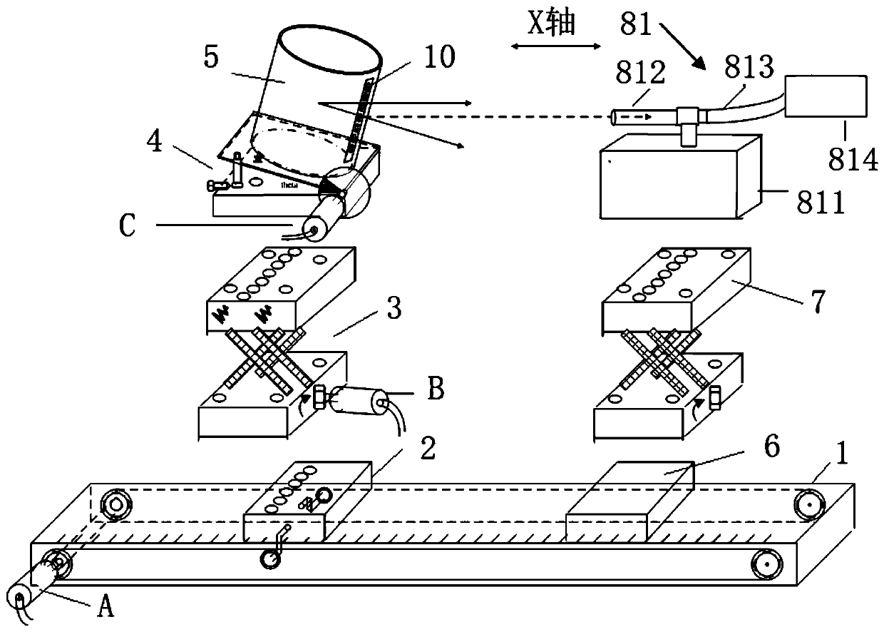
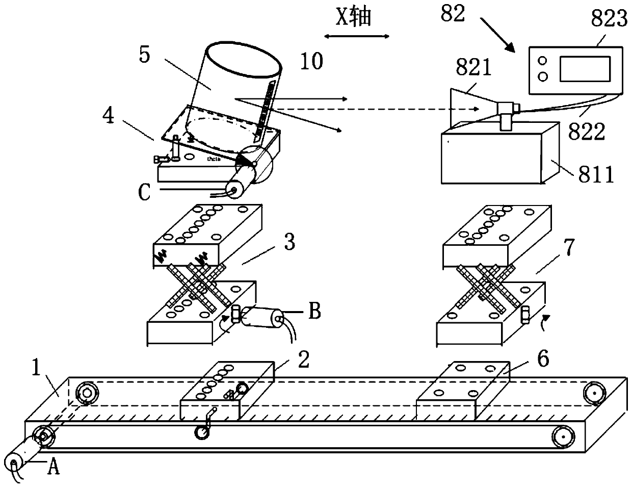
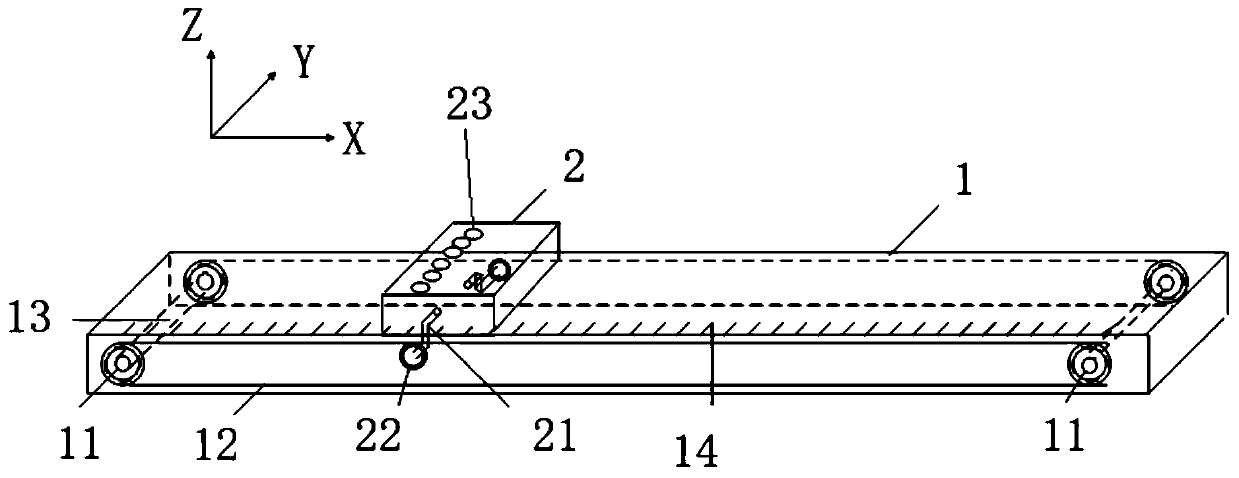
[0069] Such as Figure 1-2 Shown is a power test device based on a forward tilt beam according to an embodiment of the present invention, which is used to test the power of the forward tilt beam to be tested, including a support platform 1, installed on the support platform 1 from bottom to top The X-direction mobile stage 2, the first lifting bracket 3, the triangular tilting bracket 4 and the antenna bracket 5 connected in sequence, and the fixed stage 6 and the second lifting bracket installed on the support platform 1 and connected sequentially from bottom to top 7 and switchable laser emitting unit 81 and millimeter wave transceiver unit 82. An antenna to be tested 10 is mounted on the antenna bracket 5, and the antenna to be tested 10 is a mil...


PUM


Abstract

The invention provides a power testing device based on a forward-tilting beam. The power testing device comprises a supporting platform, and an X-direction moving carrying platform, a first lifting support, a triangular tilting support and an antenna support which are installed on the supporting platform and sequentially connected from bottom to top, and a fixed carrying platform, a second liftingsupport, a switchable laser emitting unit and a switchable millimeter wave receiving and transmitting unit which are installed on the supporting platform and sequentially connected from bottom to top, wherein the second lifting support and the first lifting support are identical in structure, and an antenna to be tested is installed on the antenna support and is set to emit a millimeter wave forward-tilting beam to be tested. The invention further provides a corresponding power testing method. According to the power testing device based on the forward-tilting beam, the X-direction moving carrying platform, the lifting support and the triangular tilting support are adopted, the position and the forward-tilting angle [theta] of the to-be-tested antenna on the X axis and the Z axis can be accurately adjusted, accurate alignment of the forward-tilting beam of millimeter waves and the millimeter wave receiving and transmitting unit is achieved, and the power of the forward-tilting beam ofthe millimeter waves can be tested.

Description

technical field [0001] The invention belongs to the field of electronic technology, and in particular relates to a power testing device and a testing method based on a forward-tilted beam. Background technique [0002] Due to its strong ability to resist rain and fog interference, the millimeter wave detector has become one of the main technical means for modern air target detection and obstacle avoidance. Due to the short rendezvous time between the aircraft and the target during flight, the beam of the millimeter-wave detector is designed with a forward tilt, which can increase the rendezvous time and obtain a better recognition rate, which has attracted attention in modern air target detection applications. [0003] Accurate power testing technology for millimeter-wave detectors has always been a difficult problem in the development of millimeter-wave technology. Existing researches mainly focus on the test research of intelligent transportation radar. Due to the large t...

Claims


Application Information

Patent Timeline
IPC IPC(8): G01R29/10G01R22/00G01R1/04G01S7/40
CPCG01R1/0408G01R22/00G01R29/10G01S7/4008
Inventor 周健孙芸钱蓉孙晓玮
Owner SHANGHAI INST OF MICROSYSTEM & INFORMATION TECH CHINESE ACAD OF SCI
Why Eureka
Try Eureka