Method and system for determining earthquake liquefaction index
A technology of liquefaction index and determination method, which is applied in the direction of design optimization/simulation, and can solve problems such as difficult to judge, error-prone, and complex
- Summary
- Abstract
- Description
- Claims
- Application Information
AI Technical Summary
Problems solved by technology
Method used
Image
Examples
Embodiment 1
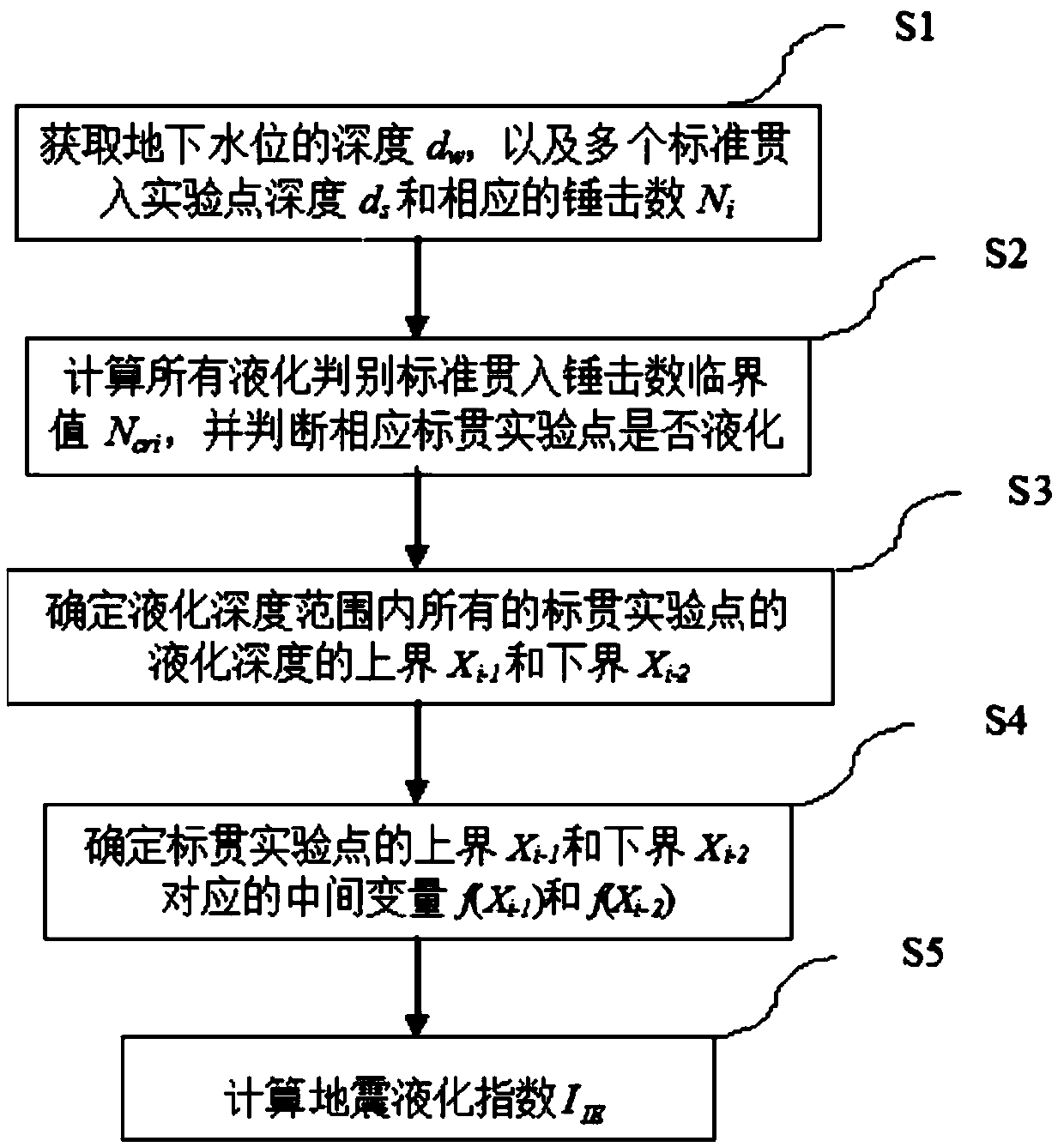
[0086] Such as figure 1 As shown, the calculation method of a kind of seismic liquefaction index of the present embodiment comprises the following steps:
[0087] S1. Obtain the depth d of the groundwater table w , and multiple standard penetration test point depths d s and the hammering number N of the corresponding standard penetration test point i .
[0088] The design basic seismic acceleration of a certain site is 0.15g, the design earthquake is grouped into the first group, the groundwater table depth is 2.0m, and the stratum distribution, standard penetration point depth and hammering number are shown in Table 1 below. Calculate the liquefaction index according to the "Code for Seismic Design of Buildings".
[0089] Table 1 Stratum distribution, standard penetration point depth and hammering number
[0090]
[0091]
[0092] According to 4.3.5 of "Code for Seismic Design of Buildings" (GB50011-2010), the basic seismic acceleration of the site design is 0.15g,...
Embodiment 2
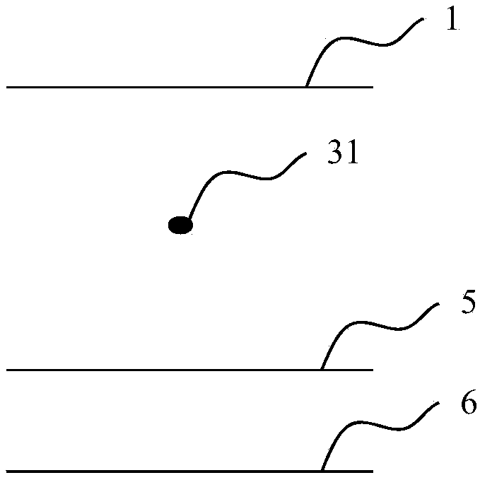
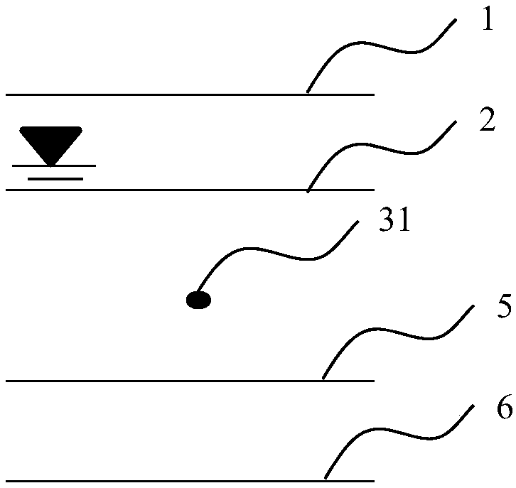
[0130] Figure 2 to Figure 5 It is a schematic diagram of determining the upper and lower boundaries of the liquefaction depth with only one standard penetration point in the same soil layer. When there is only one standard penetration experiment point between the upper and lower boundaries of the same soil layer, the upper boundary depth and groundwater level of the soil layer are selected The maximum value of the two depths is used as the upper bound X of the liquefaction depth of the standard penetration test point i-1 ; Select the minimum value of the lower boundary depth and liquefaction depth of the soil layer as the lower boundary X of the liquefaction depth of the standard penetration test point i-2 .
[0131] figure 2 It is a schematic diagram with only one standard penetration point 31 and no influence of water and liquefaction depth. At this time, the upper boundary depth of the soil layer, that is, the depth of the natural formation 1 should be selected as the ...
Embodiment 3
[0136] Figure 6 ~ Figure 9 It is a schematic diagram of determining the upper and lower boundaries of the liquefaction depth with only two standard penetration test points between the upper and lower boundaries of the same soil layer. For the shallower standard penetration test point, the maximum value of the upper boundary depth of the soil layer and the groundwater table depth is selected as the upper limit X of the liquefaction depth of the standard penetration test point i-1 ; The depth of the middle point between the depth of the deeper standard penetration test point and the depth of the shallower standard penetration test point is taken as the lower bound of the liquefaction depth of the standard penetration test point X i-2 ; For the deeper standard penetration test point, the depth of the middle point between the depth of the deeper standard penetration test point and the depth of the shallower standard penetration test point is taken as the upper bound X of the liqu...
PUM
 Abstract
Description
Claims
Application Information
 - R&D
- Intellectual Property
- Life Sciences
- Materials
- Tech Scout
- Unparalleled Data Quality
- Higher Quality Content
- 60% Fewer Hallucinations
Browse by: Latest US Patents, China's latest patents, Technical Efficacy Thesaurus, Application Domain, Technology Topic, Popular Technical Reports.
© 2025 PatSnap. All rights reserved.Legal|Privacy policy|Modern Slavery Act Transparency Statement|Sitemap|About US| Contact US: help@patsnap.com


