Magnetofluid electromagnetic induction electricity taking device

A technology of electromagnetic induction and power extraction device, applied in electromechanical devices, electrical components, etc., can solve the problems of low efficiency of CT extraction of electromagnetic induction, great influence of electromagnetic induction sensitivity and data accuracy, application limitations, etc., to protect green Energy saving and environmental protection, material production pollution reduction, loop magnetic adjustable effect

Active Publication Date: 2020-07-03
SHANDONG LANDONG INTELLIGENT TECH CO LTD
View PDF5 Cites 3 Cited by
  • Summary
  • Abstract
  • Description
  • Claims
  • Application Information

AI Technical Summary

Problems solved by technology

[0007] 1. The multi-layer winding method of permalloy soft iron belt is adopted. Because there is a large gap in the overlap of the iron belt multi-circle winding, the magnetic induction efficiency of CT is low, and the electromagnetic induction sensitivity and data of the wireless data measurement and control sensor device are low. The accuracy of the sensor has a great influence, for example, the working current for some induction needs to be above 3A in order to produce effective electromagnetic induction intensity;
[0008] 2. The induction power-taking method of hard magnetic ring passing through copper wire is adopted, or because there is no safe and reliable transformation space for some electrical and power equipment on-site environment, or it is not allowed to carry out on-site assembly work such as equipment transformation, threading and winding power wires, etc., resulting in The application of the inductive power-taking method in which the hard magnetic ring is threaded and surrounded is greatly limited

Method used


Image

  • Magnetofluid electromagnetic induction electricity taking device
  • Magnetofluid electromagnetic induction electricity taking device
  • Magnetofluid electromagnetic induction electricity taking device

Examples


Embodiment 1

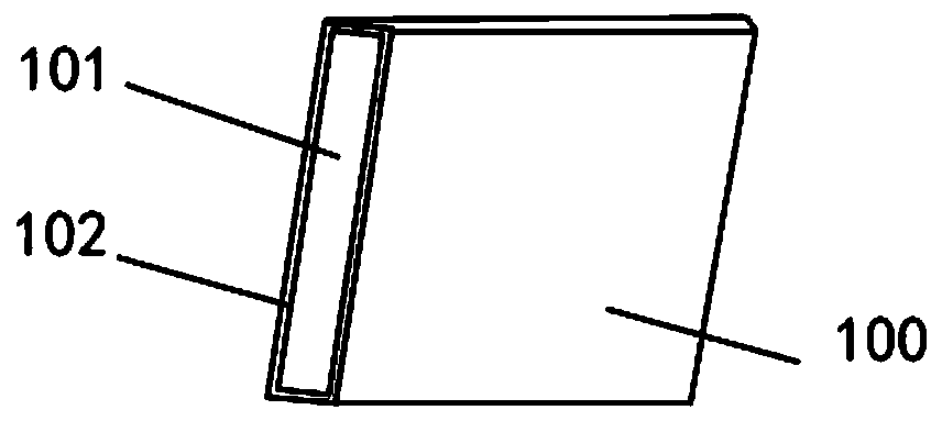
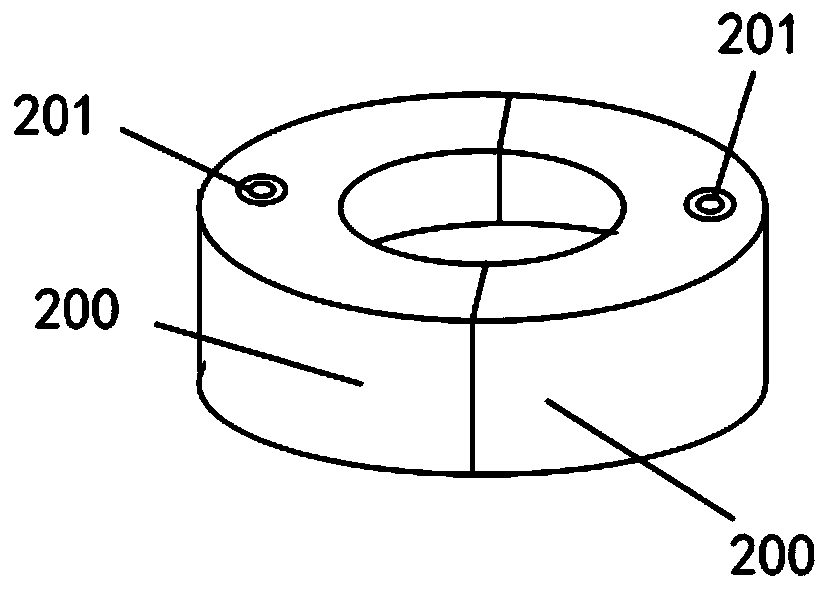
[0035] In a typical implementation of the present invention, a magnetic fluid electromagnetic induction power-taking device may have a strip shape, such as figure 1 As shown, it can also be ring-shaped, such as figure 2 Shown

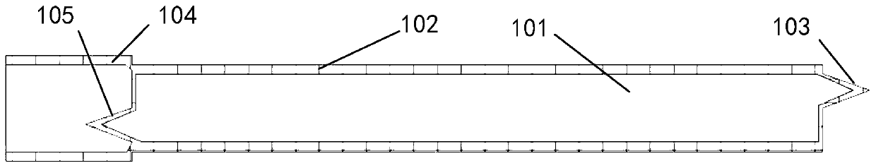
[0036] figure 1 The belt-shaped power-taking device is the magnetic fluid belt 100, such as image 3 As shown, the magnetic fluid tape 100 is composed of a magnetic fluid 101, a liquid storage housing 102, an outer piercing joint 103 with a ring, a sealing sleeve 104 with a ring, and an inner piercing joint 105 with a ring.

[0037] The liquid storage housing 102 contains the magnetic liquid 101, one end of the liquid storage housing 102 is provided with a ring outer piercing joint 103, the other end of the liquid storage housing 102 is provided with a ring sealing sleeve 104, and the end of the liquid storage housing 102 and the ring sealing sleeve 104 is connected An inner piercing joint 105 with a loop is also fixed, and the piercing joint 105 with a loop...

Embodiment 2

[0049] figure 2 The ring-shaped power take-off device is the magnetic liquid ring 200. The magnetic liquid ring 200 can be an integrated liquid storage ring structure in the ring, that is, it is formed by a ring-shaped liquid storage shell, and the ring-shaped liquid storage shell contains the magnetic liquid. The liquid storage housing is provided with a liquid injection hole 201, which is used for infusion of magnetic liquid.

[0050] The magnetic fluid ring 200 can also be composed of two semi-ring bodies with an independently sealed internal liquid storage structure, or a plurality of independent segmented ring bodies to form a magnetic body ring structure. Each segmented ring body has an independently sealed liquid storage shell, which is filled with magnetic liquid, and the liquid storage shell is provided with a liquid injection hole.

[0051] When in use, you can directly use the ring-shaped CT power-taking structure device designed and manufactured using magnetic fluid el...

Embodiment 3

[0054] Such as Figure 4 As shown, on the basis of embodiment 1, a magnetic induction structure 106 is added to the outer circumference of the liquid storage housing 102. The magnetic induction structure 106 is sleeved on the outer circumference of the liquid storage housing 102. The magnetic induction structure 106 has a liquid storage cavity, and the liquid storage cavity is There is a magnetic liquid, and the magnetic sensing structure 106 is provided with a liquid injection hole 107 for filling the magnetic liquid.

[0055] The magnetic induction structure is only arranged around one circle of the liquid storage shell, and it is not necessary to wind multiple circles. This structure enhances the magnetism of the magnetic fluid loop in the magnetic fluid with the ring, and enhances the magnetic induction intensity.


PUM


Abstract

The invention discloses a magnetofluid electromagnetic induction electricity taking device which comprises a liquid storage shell, magnetic liquid is contained in the liquid storage shell, an outer puncture connector with a ring is arranged at one end of the liquid storage shell, a sealing sleeve with a ring is arranged at the other end of the liquid storage shell, and an inner puncture connectorwith a ring is further fixedly arranged at the end, connected with the sealing sleeve with the ring, of the liquid storage shell. The device adopts magnetic fluid to take electricity through electromagnetic induction, and is strong in magnetism, strong in appearance shape plasticity and wider in application range.

Description

Technical field [0001] The present disclosure belongs to the technical field of electric power distribution automation, and in particular relates to a magnetic fluid electromagnetic induction power taking device. Background technique [0002] In the field of electric power distribution automation technology, the demand for the transformation of grid power equipment (such as overhead transmission cables, ring mains, electric control cabinets, etc.) with intelligent wireless data measurement and control sensing devices continues to expand, and its intelligent wireless Data measurement and control devices (such as temperature measurement front-end sensing units) involved in low-power CT power-taking methods are widely used. [0003] At present, there are two main ways to obtain electricity for electromagnetic induction devices of low-power CT taking electricity: [0004] 1. The induction power-supply style with multiple windings of ultra-thin permalloy soft iron tape; [0005] 2. Adopt ...

Claims


Application Information

Patent Timeline
Patent Type & Authority Applications(China)
IPC IPC(8): H02K44/12
CPCH02K44/12
Inventor 潘宁孟凡镇张鹏袭祥泉
Owner SHANDONG LANDONG INTELLIGENT TECH CO LTD
Why Eureka
Try Eureka