
Agricultural machinery for threshing various crops

A technology for crops and agricultural machinery is applied to various crop threshing agricultural machinery. It can solve problems such as increasing production cost and difficulty, and increasing work efficiency.

Inactive Publication Date: 2020-07-07
任莉颖
View PDF0 Cites 0 Cited by
  • Summary
  • Abstract
  • Description
  • Claims
  • Application Information

AI Technical Summary

Problems solved by technology

[0002] A thresher is a harvesting machine, which refers to a machine that can separate crop grains from stalks, and mainly refers to a harvesting machine for grain crops. Efficiency, which greatly increases the production cost and production difficulty. When the roller is repaired, it is also necessary to replace the specific roller

Method used


Image

  • Agricultural machinery for threshing various crops
  • Agricultural machinery for threshing various crops
  • Agricultural machinery for threshing various crops

Examples


specific Embodiment approach 1

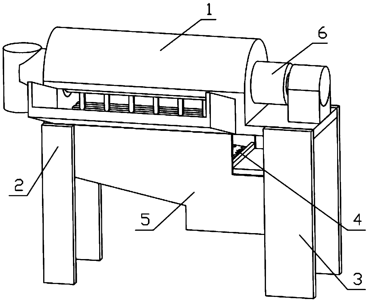
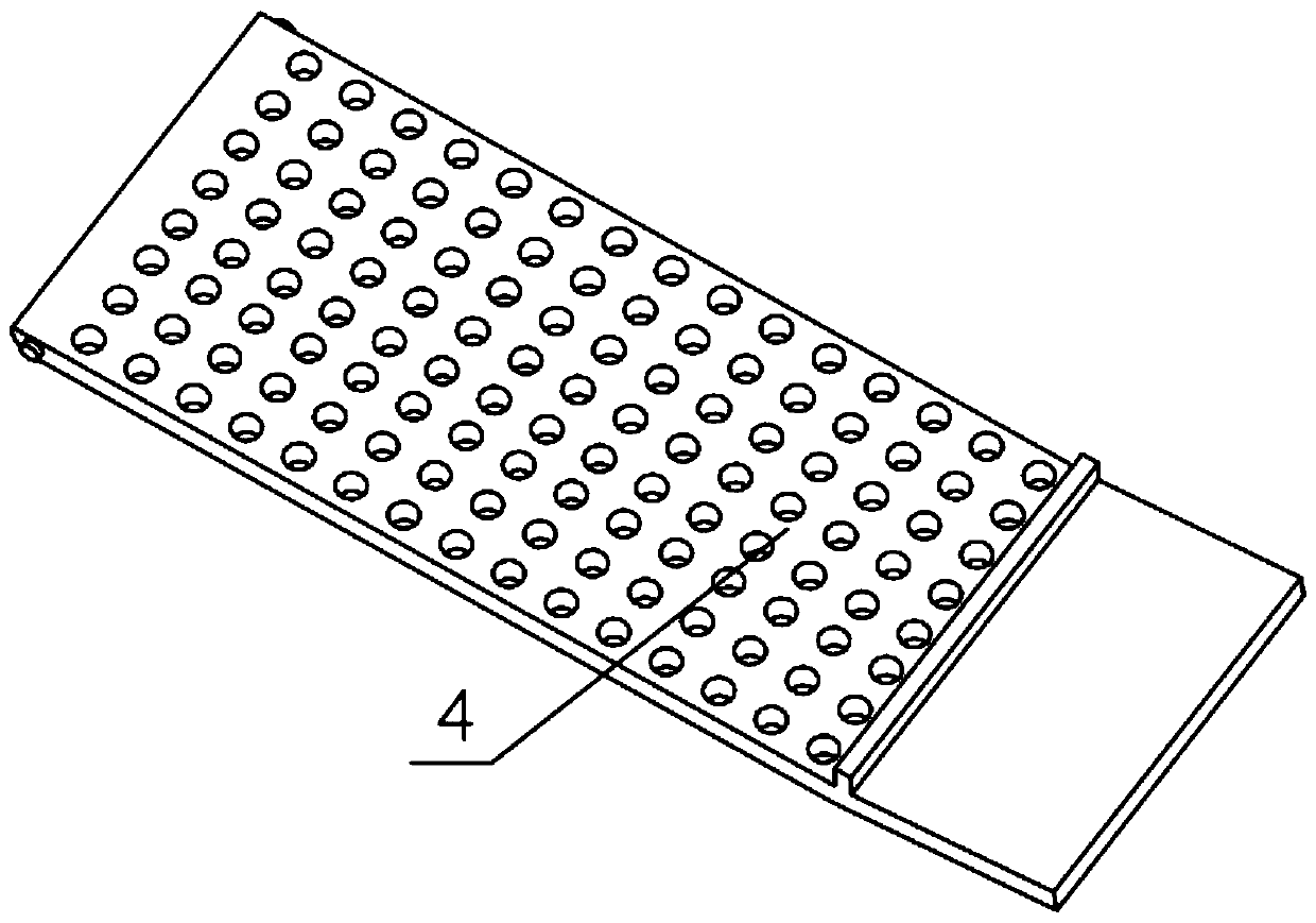
[0033] Combine below Figure 1-13 Description of this embodiment, a variety of agricultural machinery for threshing crops, including a feed seal shell 1, a front support leg 2, a rear support leg 3, a grain filter plate 4 and a bottom seal shell 5, the feed seal shell 1 and The bottom sealing shell 5 is fixedly connected, the bottom sealing shell 5 is fixedly connected with the front supporting leg 2, the feeding sealing shell 1 is fixedly connected with the rear supporting leg 3, and the grain filter plate 4 is rotatably installed in the concave hole provided on the bottom sealing shell 5. On the tank, the threshing mechanism 6 is installed on the feeding sealing shell 1.

specific Embodiment approach 2

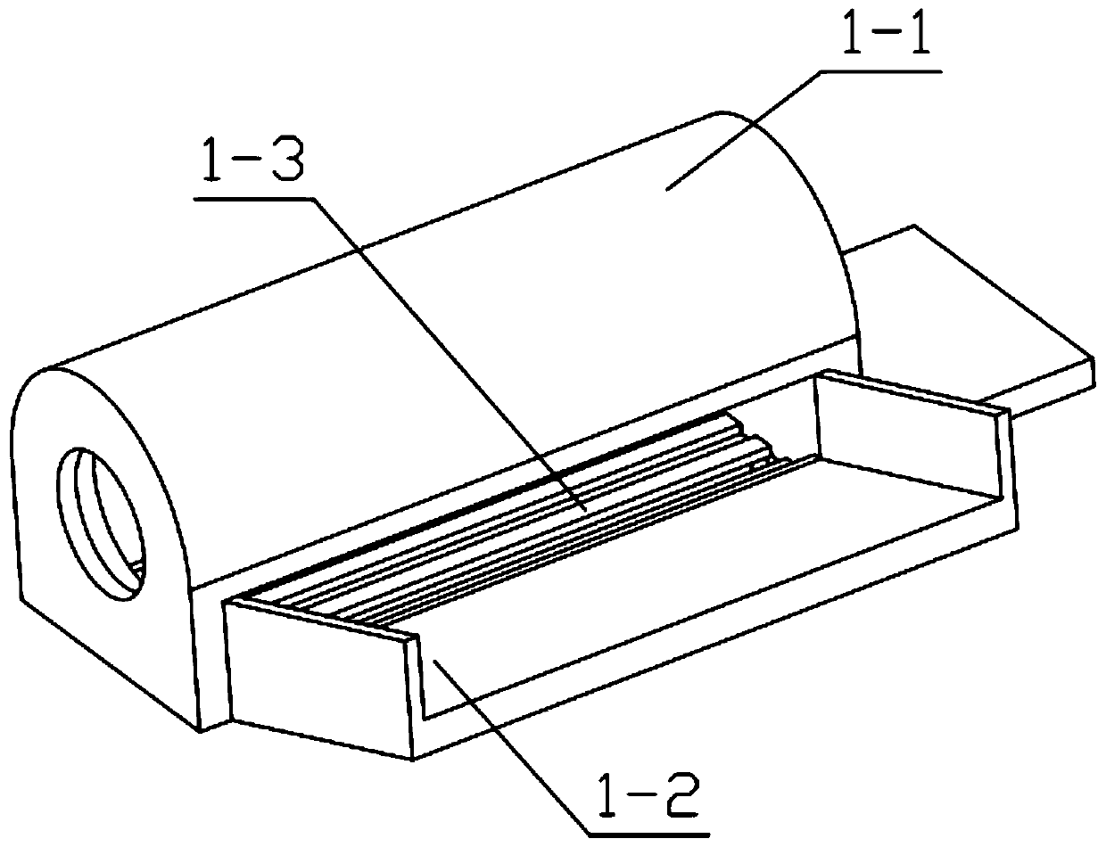
[0035] Combine below Figure 1-13 Describe this embodiment, this embodiment will further explain Embodiment 1, the described feed sealing shell 1 includes main sealing cover 1-1, feed pallet 1-2, preliminary screening grate 1-3, feed pallet The plate 1-2 is fixedly installed on the main sealing cover 1-1, the preliminary screening grid 1-3 is fixedly installed on the main sealing cover 1-1, and the preliminary screening grid 1-3 plays the role of a preliminary block to prevent the The crops undergoing threshing operations fall below.

specific Embodiment approach 3

[0037] Combine below Figure 1-13 Describe this embodiment, this embodiment will further explain the first embodiment, the bottom sealing shell 5 includes the sealing shell main body 5-1, fan grille 5-2, ash discharge grille 5-3, fan assembly 5- 4. The displacement simple adjustment assembly 5-5, the ash discharge grid 5-3 is fixedly installed on the main body 5-1 of the sealing shell, the fan grid 5-2 is fixedly installed on the main body 5-1 of the sealing shell, and the fan assembly 5- 4 Installed on the main body 5-1 of the sealed case, the simple displacement adjustment assembly 5-5 is installed on the main body 5-1 of the sealed case; the fan assembly 5-4 includes a fan motor 5-4-1, a cam 5-4-2, Fan 5-4-3, cam 5-4-2 are fixedly installed on the output end of fan motor 5-4-1, cam 5-4-2 is fixedly connected with fan 5-4-3, fan motor 5-4-1 Fixedly installed on the main body 5-1 of the sealed shell, the cam 5-4-2 is in contact with the grain filter plate 4; the displacement...


PUM


Abstract

The invention relates to an agricultural machinery device, in particular to an agricultural machinery for threshing various crops. The agricultural machinery for threshing various crops comprises a feeding sealed casing, front supporting legs, rear supporting legs, a cereal filter plate and a bottom end sealed casing, wherein the feeding sealed casing is fixedly connected with the bottom end sealed casing; the bottom end sealed casing is fixedly connected with the front supporting legs; the feeding sealed casing is fixedly connected with the rear supporting legs; the cereal filter plate is rotatably mounted on a groove in the bottom end sealed casing; and the threshing mechanism is mounted on the feeding sealed casing. According to the agricultural machinery for threshing various crops disclosed by the invention, a manner of multi-tooth swinging is adopted, so that the working efficiency of the threshing machine is improved, and seeds are separated from straws; and the agricultural machinery for threshing various crops has the function of screening, and can effectively separate the straws and impurities from the seeds.

Description

technical field [0001] The invention relates to an agricultural machinery device, in particular to an agricultural machinery for threshing various crops. Background technique [0002] A thresher is a harvesting machine, which refers to a machine that can separate crop grains from stalks, and mainly refers to a harvesting machine for grain crops. Efficiency, which greatly increases the production cost and production difficulty. When the roller is repaired, it is also necessary to replace the specific roller. Contents of the invention [0003] The technical problem mainly solved by the present invention is to provide a variety of crop threshing agricultural machinery. This device adopts the multi-tooth swing mode to improve the working efficiency of the thresher and separate the seeds from the straw. The device has a screening function and can effectively Straw and impurities are separated from seeds. [0004] The purpose of the present invention is achieved through the fo...

Claims


Application Information

Patent Timeline
IPC IPC(8): A01F7/00A01F11/00A01F12/18A01F12/44
CPCA01F7/00A01F11/00A01F12/18A01F12/446
Inventor 任莉颖梁昱王玉彪吴国莉赵丽华王睿许耘茁赵敏志
Owner 任莉颖
Learn More