
Arm support device used for radial artery puncturing

A radial artery and arm support technology, applied in the field of arm support devices for radial artery puncture, can solve problems such as inability to patient, sore hands, and reduced convenience of radial artery puncture

Inactive Publication Date: 2020-07-07
THE SECOND AFFILIATED HOSPITAL TO NANCHANG UNIV
View PDF1 Cites 1 Cited by
  • Summary
  • Abstract
  • Description
  • Claims
  • Application Information

AI Technical Summary

Problems solved by technology

[0002] Radial artery puncture is generally used for the observation of vital signs during surgical anesthesia. It belongs to the item of invasive arterial blood pressure monitoring. When the radial artery is punctured, the puncture point of the artery is generally two centimeters above the wrist joint on the palm side of the forearm. Here The arterial pulse is the most obvious. The radial artery puncture three-point positioning method is to make the patient’s wrist dorsiflexed and the wrist straightened to maximize the exposure of the radial artery, and then use the index finger and middle finger of the left hand to locate the most obvious pulse. Feel the strongest pulsation point of the radial artery. After confirming the position, move the index finger away, and slowly insert the puncture needle into the radial artery at a 45-degree angle. When the back blood is bright red and the needle tube feels pulsating, it indicates that the puncture is successful. Some radial arteries do not have arm support parts during the puncture process. When the medical staff operate for a long time, it is easy to cause soreness in the hands of the patient, which reduces the convenience of radial artery puncture and cannot bring comfort to the patient.

Method used


Image

  • Arm support device used for radial artery puncturing
  • Arm support device used for radial artery puncturing
  • Arm support device used for radial artery puncturing

Examples


Embodiment

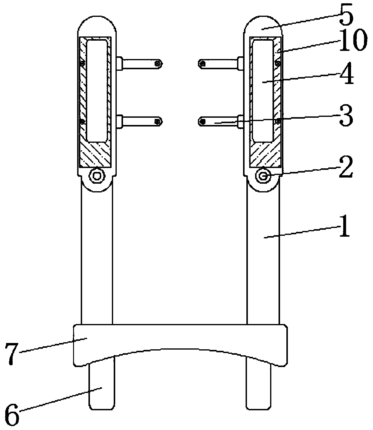
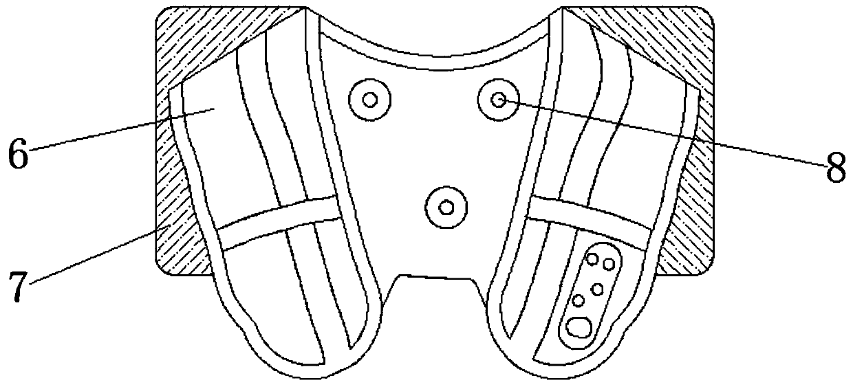
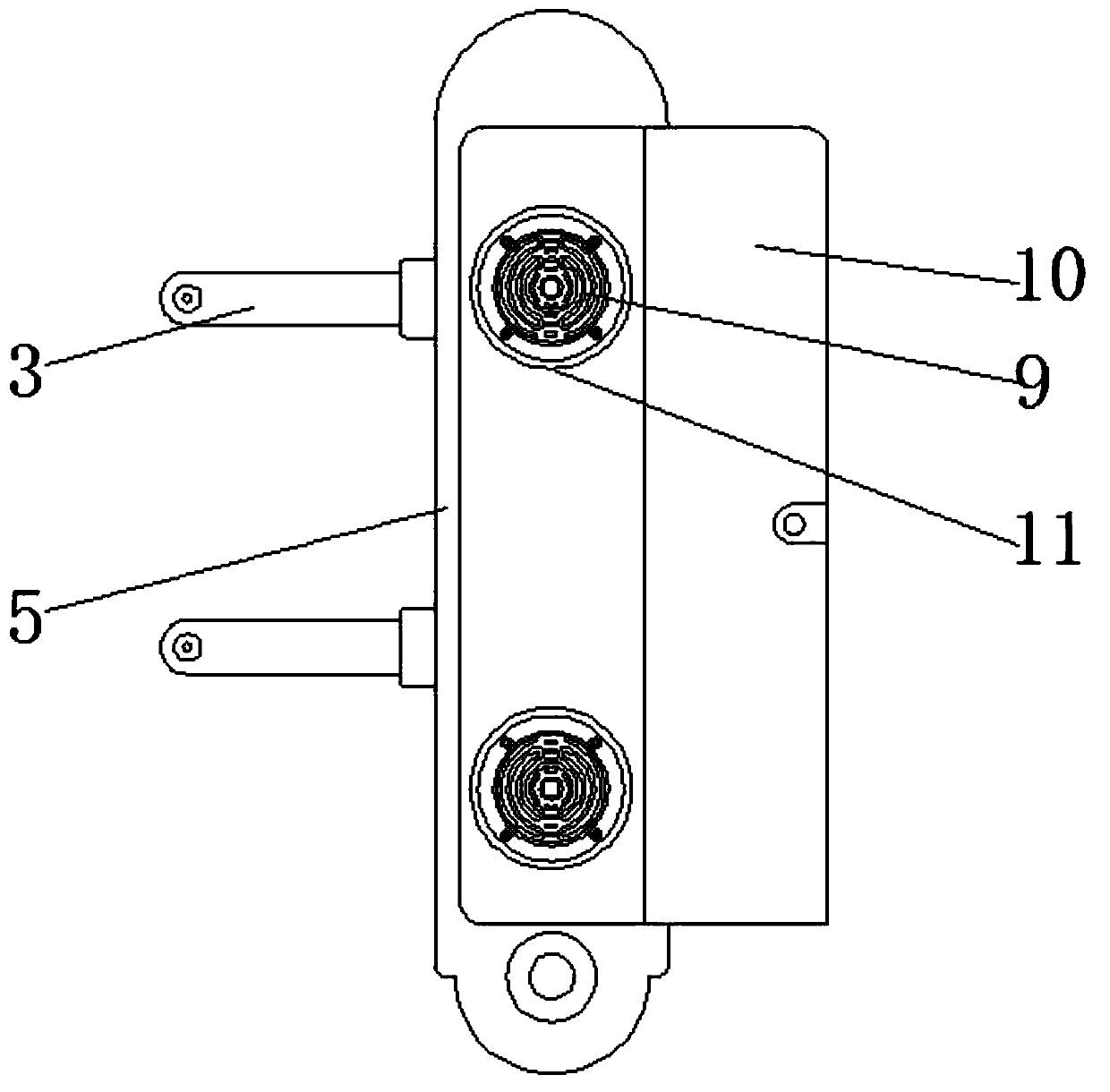
[0019] See Figure 1-3 The present invention provides a technical solution: an arm support device for radial artery puncture, comprising a first tray 1, a second tray 5 is connected to the top of the first tray 1, and the first tray 1 and the second tray 5 are rotated The shaft 2 is rotatably connected, the bottom of the first tray 1 is installed with a clamping plate 7 through bolts, and the end of the clamping plate 7 away from the first tray 1 is installed with a shoulder strap 6 through bolts.

[0020] The model of the heating plate 11 that needs to be used in this embodiment has been disclosed in an anti-freezing and anti-theft water meter (announcement number CN205642517U, announcement date October 12, 2016) disclosed in the application CN201620458295.1. The model of the shoulder strap 6 is G375 , The model of massager 8 is MLR-9992.

[0021] In this embodiment, when the medical staff needs to perform the radial artery puncture operation on the patient, they first place the ...


PUM


Abstract

The invention belongs to the technical field of medical instruments, and particularly relates to an arm support device used for radial artery puncturing. The arm support device used for radial arterypuncturing comprises first trays, wherein second trays are installed on the tops of the first trays, the first trays and the second trays are rotatably connected through rotating shafts, a clamping board is installed on the bottoms of the first trays, and a double-shoulder strap is installed at the end, away from the first trays, of the clamping board. When a patient needs to be subjected to radial artery puncturing surgery, firstly, the clamping board is placed above the chest of the patient, then the patient carries the double-shoulder strap connected with the clamping board on the shoulders, thus the clamping board is fixed onto the chest of the patient, then the second trays in cooperation with the rotating shafts are made to be at the levels of the first trays, and then the patient can put the arms on the first trays and the second trays so that the arms can be supported, aching pain of the hands in a radial artery puncturing process is avoided, and comfort of the patient during radial artery puncturing is enhanced.

Description

Technical field [0001] The invention belongs to the technical field of medical devices, and particularly relates to an arm rest device for radial artery puncture. Background technique [0002] Radial artery puncture is generally used for the observation of vital signs during surgical anesthesia. It is a project of invasive arterial blood pressure monitoring. When radial artery puncture is performed, the puncture point of the artery is generally two centimeters above the volar wrist joint of the forearm. The arterial pulsation is the most obvious. The three-point positioning method of radial artery puncture is to make the patient dorsiflexion of the wrist and straighten the wrist to expose the position of the radial artery to the maximum. Then use the left index finger and the middle designated position to locate the most obvious pulsation, use the index finger Feel the strongest point of radial artery pulsation. After finalizing the position, move your index finger away and slowl...

Claims


Application Information

Patent Timeline
IPC IPC(8): A61B5/0215A61B5/00A61H7/00
CPCA61B5/0215A61B5/702A61H7/00A61H2201/0207A61H2201/0228
Inventor 张静余鹏余树春华福洲魏根肖凡刘琴黄丹
Owner THE SECOND AFFILIATED HOSPITAL TO NANCHANG UNIV
Learn More