Valve contraction ring system

A valve and contraction ring technology, applied in the field of medical devices, can solve problems such as inability to reduce the volume of the left ventricle and unsatisfactory treatment effects

Pending Publication Date: 2020-07-07
HANGZHOU VALGEN MEDTECH CO LTD
View PDF0 Cites 2 Cited by
  • Summary
  • Abstract
  • Description
  • Claims
  • Application Information

AI Technical Summary

Problems solved by technology

However, in the prior art, in patients with functional mitral valve regurgitation and heart failure accompanied by dilated left ventricle, the

Method used


Image

  • Valve contraction ring system
  • Valve contraction ring system
  • Valve contraction ring system

Examples


Embodiment Construction

[0035] The following description is a preferred embodiment of the present invention, it should be pointed out that for those skilled in the art, without departing from the principle of the present invention, some improvements and modifications can also be made, and these improvements and modifications are also considered Be the protection scope of the present invention.

[0036] In order to describe the structure of the valve constriction ring system more clearly, the terms "proximal end" and "distal end" are defined here as commonly used terms in the field of interventional medicine. Specifically, "distal end" means the end far away from the operator during the surgical operation, and "near end" means the end close to the operator during the surgical operation.

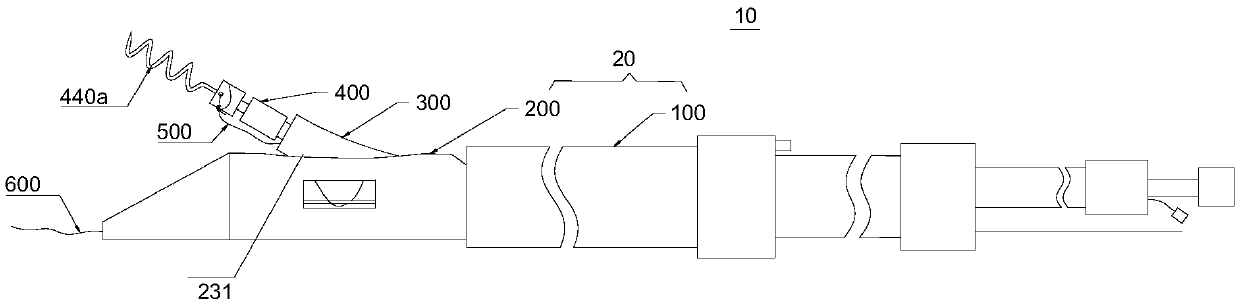
[0037] see figure 2 The first embodiment of the present invention provides a valve constriction system 10, including a positioning device 20, a delivery device 300, an anchoring device 400, and a tightening wire 50...


PUM


Abstract

The invention provides a valve contraction ring system. The system includes a positioning device, a conveying device, an anchoring device and a tightening line, and the anchoring device includes a plurality of anchoring components; the positioning device is provided with a plurality of axially arranged windows, the positioning device is positioned on a targeting part, and the plurality of windowsface different positions of the targeting part; the conveying device conveys the plurality of anchoring components along the positioning device to the different positions of the targeting part throughthe plurality of windows, respectively; the anchoring device fix the anchoring components passing through each window at the different positions of the targeting part in sequence; and the tighteningline is used to connect and tighten a plurality of anchoring components fixed at the different positions of the targeting part in series, so that the circumference of the targeting part is contracted.According to the valve contraction ring system provided by the invention, the anchoring device extends from different windows to fix the anchoring components at the different positions of the targeting part, and the targeting part is tightened by the tightening line, so that the effect of contracting the circumference of the targeting part is realized.

Description

technical field [0001] The invention relates to the field of medical devices, in particular to a valve contraction ring system. Background technique [0002] Such as figure 1 As shown, the human heart is composed of the left ventricle (RV) and the right atrium (RA), and the left ventricle includes the left ventricle (LV) and the left atrium (LA). The mitral valve is a "one-way valve" between the left atrium and left ventricle, consisting of the annulus (MVA), anterior leaflet (AML), posterior leaflet (PML), chordae (CT) and papillary muscle (PM). The annulus is between the left atrium and the left ventricle. The anterior leaflet and the posterior leaflet are connected to the annulus. There are multiple chordae (CT) on the two leaflets, and the other end of the chordae is connected to the papillary muscle. During the beating process of the heart, the anterior and posterior leaflets of the normal mitral valve are in open and closed cyclical motions, thereby ensuring blood ci...

Claims


Application Information

Patent Timeline
IPC IPC(8): A61F2/24
CPCA61F2/2442A61F2/2466
Inventor 张庭超郭荣辉
Owner HANGZHOU VALGEN MEDTECH CO LTD
Why Eureka
Try Eureka