
Adsorption device and desorption system

An adsorption device and desorption technology, applied in gas treatment, membrane technology, dispersed particle separation, etc., can solve problems such as high energy consumption, high requirements for terminal treatment equipment, and large fluctuations in concentration changes

Pending Publication Date: 2020-07-07
VERBOCA ENERGY SAVING TECH CO LTD
View PDF9 Cites 0 Cited by
  • Summary
  • Abstract
  • Description
  • Claims
  • Application Information

AI Technical Summary

Problems solved by technology

During the desorption operation, the adsorbent desorbs as a whole, and the adsorbent as a whole absorbs heat and obtains enough energy before desorption begins. At the same time, the exhaust gas concentration of the desorption operation shows a single-wave peak distribution, and the concentration change fluctuates greatly. The terminal processing equipment has high requirements and consumes a lot of energy

Method used


Image

  • Adsorption device and desorption system
  • Adsorption device and desorption system
  • Adsorption device and desorption system

Examples


Embodiment 1

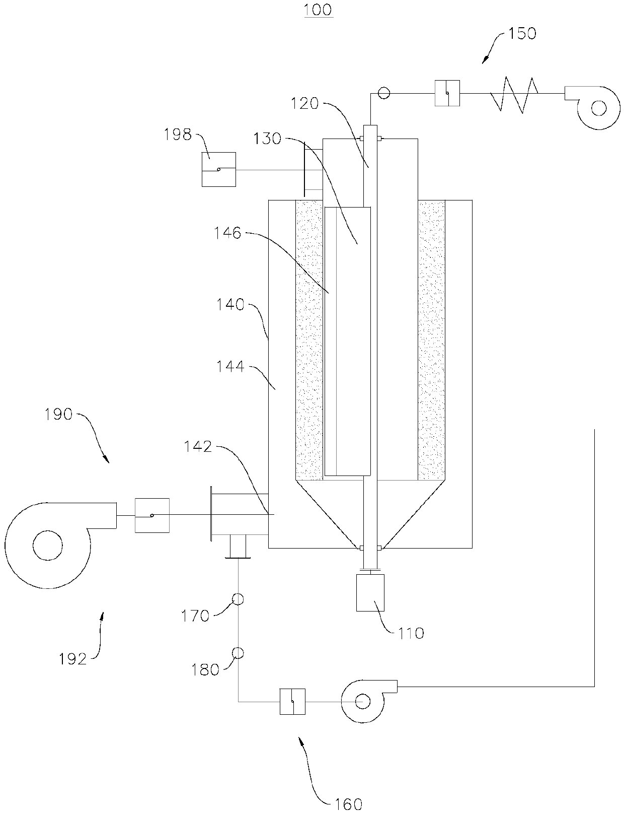
[0044] see figure 1 , this embodiment provides an adsorption device 100, and the adsorption device 100 provided by this embodiment can improve the effect of desorption.

[0045]The adsorption device 100 provided in this embodiment can adsorb organic molecules in the organic raw gas, filter the organic raw gas into filtered gas, and also allow the raw gas to absorb organic molecules in the adsorption device 100 to form high-concentration organic waste gas.

[0046] see figure 1 , in this embodiment, the adsorption device 100 includes a driver 110, a nozzle 120, an adsorption layer 130 and a housing 140, the adsorption layer 130 is arranged in the housing 140, and the housing 140 is divided into an inner cavity 144 and an outer cavity 146, The nozzle 120 is disposed within the inner cavity 144;

[0047] The nozzle 120 is used to introduce the preheated raw gas into the inner chamber 144;

[0048] The driver 110 is connected to the nozzle 120, and is used to drive the nozzle 1...

Embodiment 2

[0081] see Figure 5 , this embodiment provides a desorption system 10, and the desorption system 10 provided by this embodiment can improve the effect of desorption.

[0082] For brief description, for the parts not mentioned in this embodiment, reference may be made to Embodiment 1.

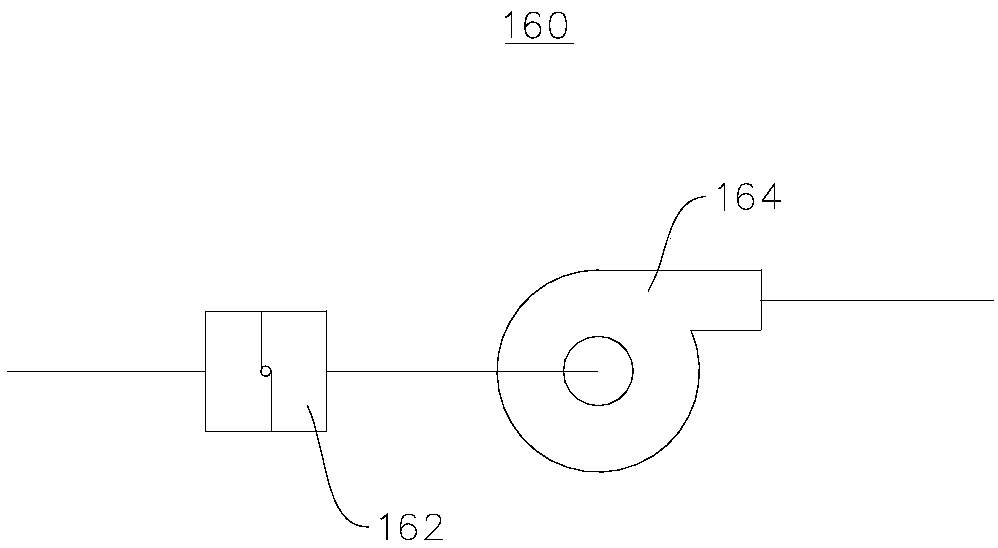
[0083] In this embodiment, the desorption system 10 includes a treatment device 200 and the adsorption device 100 provided in the first embodiment. The treatment device 200 is connected with the outlet fan 164 for treating organic waste gas.


PUM


Abstract

The invention provides an adsorption device and a desorption system, and relates to the field of waste gas treatment. The adsorption device comprises a driver, a nozzle, an adsorption layer and a shell; the adsorption layer is arranged in the shell and divides the shell into an inner cavity and an outer cavity, and the nozzle is arranged in the inner cavity; during desorption operation, the nozzleis used for guiding preheated raw material gas into the inner cavity; the driver is connected with the nozzle and used for driving the nozzle to rotate, so that the raw material gas is sequentially diffused to the adsorption layer and the outer cavity; during adsorption operation, the adsorption layer is used for adsorbing organic molecules, and during desorption operation, when the raw materialgas diffuses to the adsorption layer, the raw material gas brings out the organic molecules in the adsorption layer to form organic waste gas, and the organic waste gas diffuses to the outer cavity; and a desorption air outlet is formed in the shell and communicates with the outer cavity, and organic waste gas is exhausted from the desorption air outlet. The adsorption device provided by the invention can improve the desorption effect.

Description

technical field [0001] The invention relates to the field of waste gas treatment, in particular to an adsorption device and a desorption system. Background technique [0002] The existing organic waste gas (VOCs) adsorption devices mainly include fixed bed adsorption devices and rotary enrichment devices. [0003] For fixed bed adsorption devices, the amount of adsorbent depends on the air volume and quality of adsorption, and generally the amount of adsorbent is relatively large. During the desorption operation, the adsorbent desorbs as a whole, and the adsorbent as a whole absorbs heat and obtains enough energy before desorption begins. At the same time, the exhaust gas concentration of the desorption operation shows a single-wave peak distribution, and the concentration change fluctuates greatly. The terminal processing equipment has high requirements and consumes a lot of energy. Contents of the invention [0004] The object of the present invention is to provide an ...

Claims


Application Information

Patent Timeline
Patent Type & Authority Applications(China)
IPC IPC(8): B01D53/04
CPCB01D53/04B01D2257/70B01D2259/40086
Inventor 严翔简甦张桂超
Owner VERBOCA ENERGY SAVING TECH CO LTD
Learn More