Welding equipment for intelligent pantograph carbon slide plates and welding method thereof

A technology of pantograph carbon slide plate and welding equipment, applied in welding equipment, welding equipment, auxiliary welding equipment, etc., can solve problems such as damage to metal support brackets

Active Publication Date: 2020-07-07
DATONG XINCHENG NEW MATERIAL CO LTD
View PDF10 Cites 0 Cited by
  • Summary
  • Abstract
  • Description
  • Claims
  • Application Information

AI Technical Summary

Problems solved by technology

During the use of existing carbon skateboard welding equipment, arcs often occur between the catenary and the metal support bracket of the carbon skateboard, thus causing damage to the metal support bracket

Method used


Image

  • Welding equipment for intelligent pantograph carbon slide plates and welding method thereof
  • Welding equipment for intelligent pantograph carbon slide plates and welding method thereof
  • Welding equipment for intelligent pantograph carbon slide plates and welding method thereof

Examples


Embodiment 1

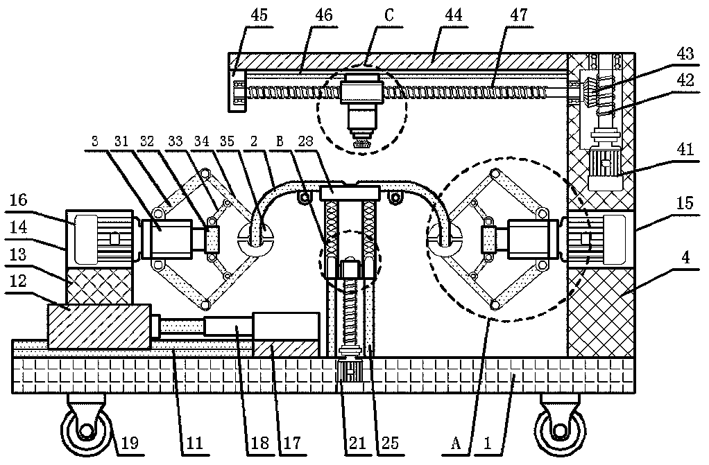
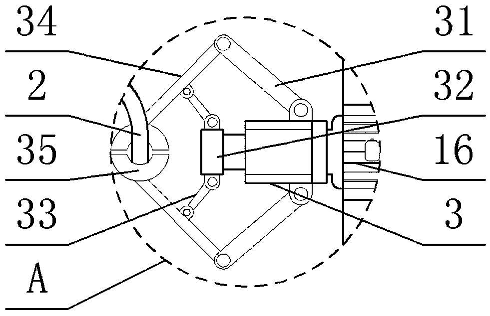
[0034] Embodiment 1: see Figure 1-4, a welding equipment for intelligent pantograph carbon slides, including a bottom plate 1, the bottom plate 1 is a rectangular long plate placed horizontally and horizontally, and the middle part of the top surface of the bottom plate 1 is provided with a suspension opening facing downwards. The carbon skateboard 2, the middle part of the top surface of the bottom plate 1 is recessed with a first motor slot, the first motor 21 with the output end facing up is installed in the first motor slot, the model of the first motor 21 is YPNX90L, the The first motor 21 is movably connected to the middle part of the bottom surface of the carbon slide plate 2 through a lifting mechanism; one side of the top surface of the bottom plate 1 is provided with a limit slide rail 11 placed horizontally, and the limit slide rail 11 is a T-shaped strip, so The top surface of the limit slide rail 11 is clamped with a limit slide plate 12, the bottom surface of th...

Embodiment 2

[0043] Example 2: see Figure 5 , in the present embodiment, the present invention also proposes a welding method for welding equipment of intelligent pantograph carbon slide plate, comprising the following steps:

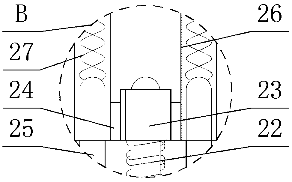
[0044] Step 1: Set the middle part of the bottom surface of the carbon slide plate 2 to be welded in the limit long slot on the top surface of the limit long plate 28, control the rotation of the motor shaft of the first motor 21, and drive the first thread cylinder through the first threaded rod 22 23 lifts, and then drives the two sliding cylinders 26 to move up and down along the slide bar 25 under the cooperation of the carbon slide 27, thereby driving the position-limiting long plate 28 to lift, so that the two ends of the carbon slide 2 are at the same height as the clamping block 35;

[0045] Step two, control the expansion and contraction of the telescopic rod of the first telescopic cylinder 18, drive the limit slide plate 12 to move laterally along the li...


PUM


Abstract

The invention discloses welding equipment for intelligent pantograph carbon slide plates. The welding equipment comprises a base plate. A first motor is movably connected with the middles of the bottom faces of the carbon slide plates through a lifting mechanism. Clamping mechanisms are installed at the output ends of second motors in a coaxial connecting mode, and a pair of clamping blocks insidethe clamping mechanism on the same side are clamped with one end of the corresponding carbon slide plate. A driving groove is formed in the top of a vertical plate in a sunken mode, and a driving assembly is installed in the driving groove. A transverse plate which is transversely placed is arranged at the top of the inner side face of the vertical plate. The invention further discloses a weldingmethod of the welding equipment for the intelligent pantograph carbon slide plates. The welding equipment for the intelligent pantograph carbon slide plates is simple in structure and convenient andfast to move, the problem that a metal supporting tray can be damaged in the welding process of the carbon slide plates is effectively solved, the operating steps are simplified through matching usageof all the mechanisms, and automatic welding efficiency is improved.

Description

technical field [0001] The invention relates to the technical field of carbon slide welding equipment, in particular to a welding equipment and a welding method for an intelligent pantograph carbon slide. Background technique [0002] The carbon skateboard and the catenary wire constitute a pair of special friction pairs that are mechanically and electrically coupled. Under normal working conditions, the carbon skateboard needs to withstand high-speed sliding, high-voltage and high-current conditions. The above-mentioned working conditions will accelerate the wear and tear of the carbon skateboard itself. When the carbon skateboard itself wears to a certain extent, the carbon skateboard may break and fall off. Once the carbon skateboard of the train fails, it will seriously endanger the safety of the train. Therefore, the carbon skateboard must be replaced in time. [0003] Carbon slides include clamping carbon slides, welded carbon slides and bonded carbon slides. The weld...

Claims


Application Information

Patent Timeline
IPC IPC(8): B23K31/02B23K37/047B23K37/02
CPCB23K31/02B23K37/0247B23K37/047
Inventor 王振国张培林武建军柴利春张作文王志辉
Owner DATONG XINCHENG NEW MATERIAL CO LTD
Why Eureka
Try Eureka