
Special-shaped part polishing device for machining

A kind of mechanical processing and special-shaped technology, applied in the direction of grinding/polishing safety device, grinding workpiece support, metal processing equipment, etc., can solve the problem of comprehensive clamping of special-shaped parts, affecting the appearance and use of special-shaped parts, and grinding errors of special-shaped parts And other issues

Inactive Publication Date: 2020-07-07
合肥锦鑫隆机械制造有限公司
View PDF6 Cites 1 Cited by
  • Summary
  • Abstract
  • Description
  • Claims
  • Application Information

AI Technical Summary

Problems solved by technology

[0003] Due to the different sizes of the special-shaped parts, it is not easy to fully clamp the special-shaped parts when clamping the special-shaped parts, so that when the special-shaped parts are polished, the position of the special-shaped parts will be shifted, resulting in the deformation of the special-shaped parts. Grinding mistakes will affect the appearance and use of special-shaped parts. In addition, the grinding of special-shaped parts will produce waste chips, which will affect the judgment of the grinding position of special-shaped parts when grinding them, resulting in the grinding of special-shaped parts. mistake

Method used


Image

  • Special-shaped part polishing device for machining
  • Special-shaped part polishing device for machining

Examples


Embodiment Construction

[0019] The following will clearly and completely describe the technical solutions in the embodiments of the present invention with reference to the accompanying drawings in the embodiments of the present invention. Obviously, the described embodiments are only some, not all, embodiments of the present invention.

[0020] In describing the present invention, it should be understood that the terms "upper", "lower", "front", "rear", "left", "right", "top", "bottom", "inner", " The orientation or positional relationship indicated by "outside", etc. is based on the orientation or positional relationship shown in the drawings, and is only for the convenience of describing the present invention and simplifying the description, rather than indicating or implying that the referred device or element must have a specific orientation, so as to Specific orientation configurations and operations, therefore, are not to be construed as limitations on the invention.

[0021] refer to Figure ...


PUM


Abstract

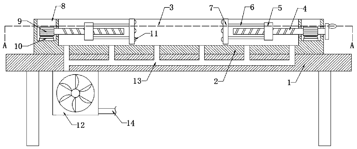
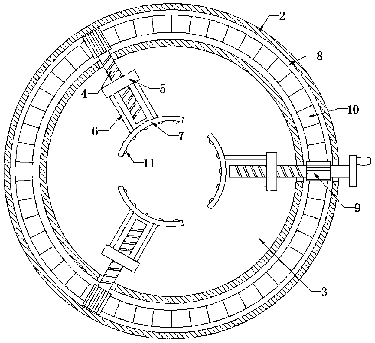
The invention discloses a special-shaped part polishing device for machining. The device comprises a base; a disc is fixedly connected to the upper end of the base, a circular groove is formed in theupper end of the disc, a plurality of lead screws are uniformly and rotatably connected to the inner wall of the circular groove, an annular groove is formed in the upper end of the disc, and a driving device for driving the plurality of lead screws to rotate synchronously is installed in the annular groove. According to the special-shaped part polishing device, annular racks, gears, hand wheels,the screw rods, sliding blocks, connecting rods and arc-shaped clamping plates are arranged, the hand wheels are rotated to enable the screw rods rotatably connected to the inner wall of the circulargroove to rotate synchronously, the special-shaped part is clamped in all sides, the problem that the position of the special-shaped part is shifted during polishing of the special-shaped part, causing polishing errors of the special-shaped part to influence the appearance and the use of the special-shaped part is avoided, scraps in the polishing process of the special-shaped part can be sucked through a fan, and the judgment of the polishing position of the special-shaped part is prevented from being influenced by the scraps.

Description

technical field [0001] The invention relates to the technical field of mechanical processing, in particular to a grinding device for special-shaped parts for mechanical processing. Background technique [0002] Machining is to change the dimensions or performance of the workpiece. In the process of machining, in order to ensure the appearance of the workpiece, the workpiece needs to be polished. For some special-shaped parts, it needs to be polished to improve its use accuracy. . [0003] Due to the different sizes of the special-shaped parts, it is not easy to fully clamp the special-shaped parts when clamping the special-shaped parts, so that when the special-shaped parts are polished, the position of the special-shaped parts will be shifted, resulting in the deformation of the special-shaped parts. Grinding mistakes will affect the appearance and use of special-shaped parts. In addition, the grinding of special-shaped parts will produce waste chips, which will affect the...

Claims


Application Information

Patent Timeline
IPC IPC(8): B24B19/00B24B41/02B24B41/06B24B55/06
CPCB24B19/00B24B41/02B24B41/06B24B41/067B24B55/06
Inventor 顾建明
Owner 合肥锦鑫隆机械制造有限公司
Learn More