Laser vision positioning correction method for cutting complex workpiece by robot

A technology for complex workpieces and robots, which is applied to manipulators, manufacturing tools, metal processing equipment, etc., and can solve problems such as defective products and workpiece cutting

Active Publication Date: 2020-07-07
TANGSHAN YINGLAI SCI & TECH
View PDF6 Cites 4 Cited by
  • Summary
  • Abstract
  • Description
  • Claims
  • Application Information

AI Technical Summary

Problems solved by technology

[0006] Aiming at the deficiencies of the prior art, the present invention provides a laser vision positioning correction method for cutting complex workpieces by robots, which solves the problem that when t...

Method used


Image

  • Laser vision positioning correction method for cutting complex workpiece by robot
  • Laser vision positioning correction method for cutting complex workpiece by robot
  • Laser vision positioning correction method for cutting complex workpiece by robot

Examples


Embodiment Construction

[0033] The following will clearly and completely describe the technical solutions in the embodiments of the present invention with reference to the accompanying drawings in the embodiments of the present invention. Obviously, the described embodiments are only some, not all, embodiments of the present invention. Based on the embodiments of the present invention, all other embodiments obtained by persons of ordinary skill in the art without making creative efforts belong to the protection scope of the present invention.

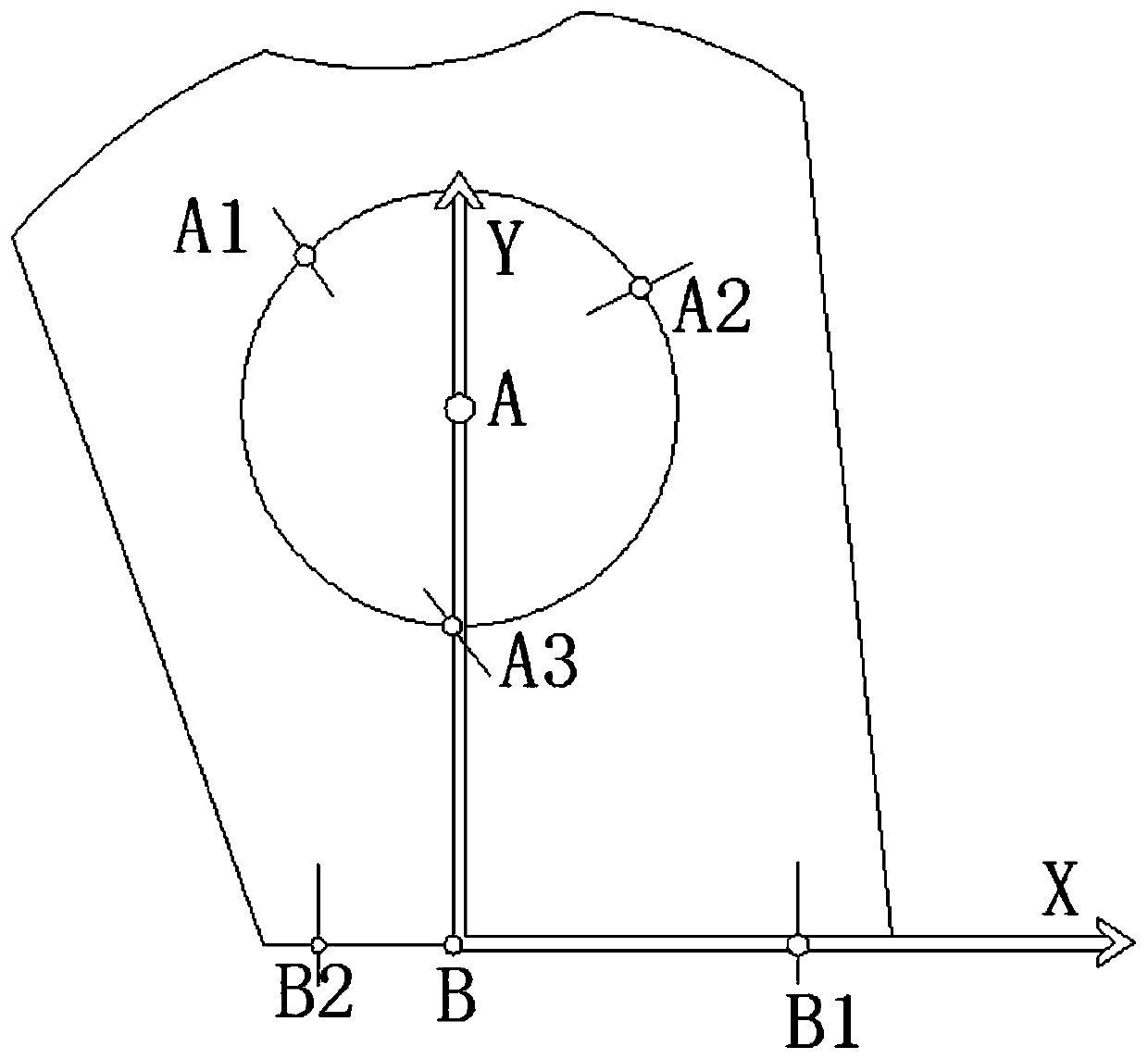
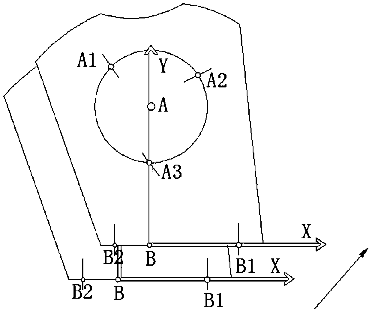
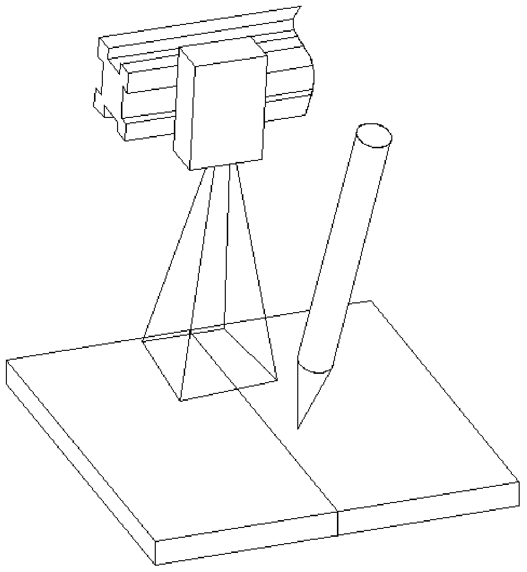
[0034] see Figure 1-3 , an embodiment of the present invention provides a technical solution: a laser vision positioning correction method for cutting complex workpieces by robots, comprising the following steps:

[0035] Step 1. Coordinate system change: switch the robot coordinate system to the world coordinate system;

[0036] Step 2. Preliminary coordinate confirmation: Try to teach the three scanning positions of the laser vision sensor on the inner cir...


PUM


Abstract

The invention discloses a laser vision positioning correction method for cutting a complex workpiece by a robot. The method comprises the following steps of step 1, changing a coordinate system, namely switching a coordinate system of the robot into a world coordinate system; step 2, confirming coordinates preliminarily, namely carrying out trial teaching on three scanning positions of a laser vision sensor on the inner circle of the workpiece in the world coordinate system, randomly determining three points and finding coordinates of the points A1, A2 and A3; and step 3, calculating a centerposition, namely calculating a center point A. The invention relates to the technical field of plasma cutting industrial robots. According to the laser vision positioning correction method for cuttingthe complex workpiece by the robot, a cutting track is cut in the workpiece coordinate system, a laser vision positioning system is applied, a workpiece coordinate system is established, and the trail teaching is carried out on the cutting (welding) track on the basis of the workpiece coordinate system, so that the welding track can be corrected only by repositioning the workpiece coordinate system through the laser vision positioning system when the workpiece is replaced, and the method is small in programming amount and easy to understand.

Description

technical field [0001] The invention relates to the technical field of plasma cutting industrial robots, in particular to a laser vision positioning correction method for cutting complex workpieces by robots. Background technique [0002] In order to meet the production needs of the locomotive heavy industry industry, the number of cutting lines for medium and thick plates is increasing day by day. At the same time, the requirements for cutting quality and cutting efficiency are also increasing. With the rapid development of global industrial automation, plasma cutting industrial robots have been widely used. . [0003] An industrial robot is a multi-joint manipulator or a multi-degree-of-freedom machine device for the industrial field. It can perform work automatically. It is a machine that realizes various functions by its own power and control capabilities. It can accept human commands or follow instructions Pre-arranged program operation, modern industrial robots can al...

Claims


Application Information

Patent Timeline
IPC IPC(8): B25J9/16B23K10/00
CPCB25J9/1697B25J9/1664B23K10/00Y02P90/02
Inventor 张晨阳么文昊何欢蔡建辉杨新宇
Owner TANGSHAN YINGLAI SCI & TECH
Why Eureka
Try Eureka