Eureka AIR delivers breakthrough ideas for toughest innovation challenges, trusted by R&D personnel around the world.

Auxiliary demolding device for injection mold as well as operation method of auxiliary demolding device

A demolding device and injection mold technology, applied in the application field of injection molds

Pending Publication Date: 2020-07-07
林冰莺
View PDF0 Cites 4 Cited by
  • Summary
  • Abstract
  • Description
  • Claims
  • Application Information

AI Technical Summary

Problems solved by technology

[0004] The purpose of the present invention is to provide an auxiliary demoulding device for injection molds and its operating method, which can solve the problem of demoulding with the help of external force when the upper and lower molds of the existing injection molds are demoulding.

Method used


Image

  • Auxiliary demolding device for injection mold as well as operation method of auxiliary demolding device
  • Auxiliary demolding device for injection mold as well as operation method of auxiliary demolding device
  • Auxiliary demolding device for injection mold as well as operation method of auxiliary demolding device

Examples


Embodiment Construction

[0038] The technical solutions of the present invention will be clearly and completely described below in conjunction with embodiments. Obviously, the described embodiments are only a part of the embodiments of the present invention, rather than all the embodiments. Based on the embodiments of the present invention, all other embodiments obtained by those of ordinary skill in the art without creative work shall fall within the protection scope of the present invention.

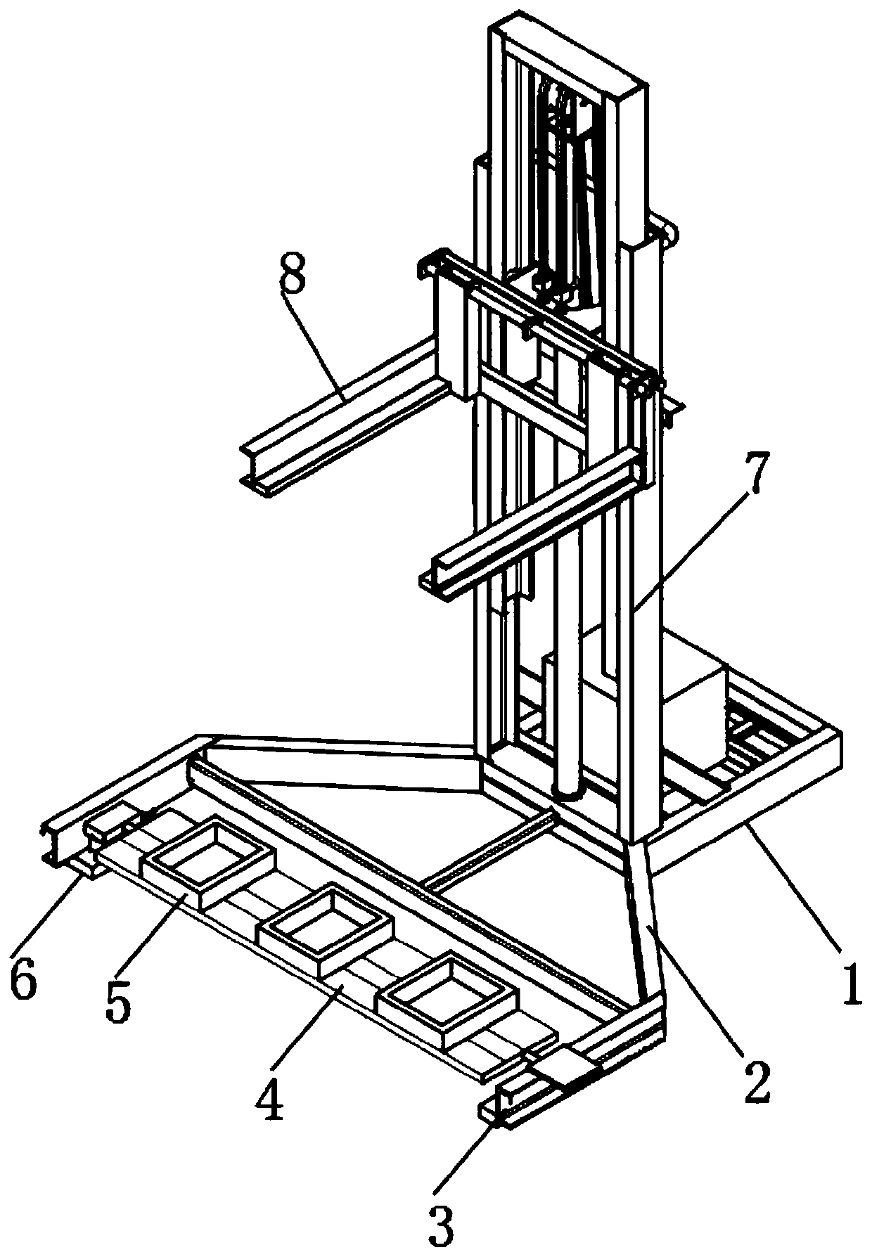
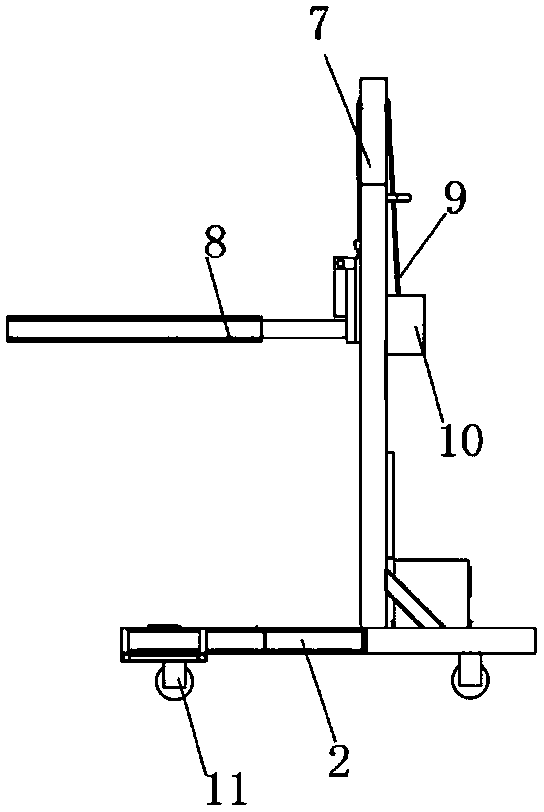
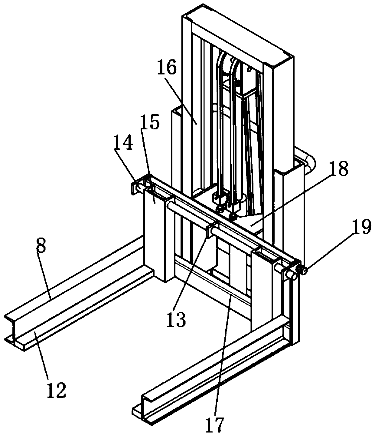
[0039] See Figure 1-9 As shown, an auxiliary demolding device for injection molds includes a base 1 and a supporting frame 2. The base 1 is fixedly installed at one end of the supporting frame 2, and both sides of the top end of the base 1 are vertically installed with supports 7, two An end plate 18 that can move up and down is installed between the two supports 7. A connecting plate is installed on the side of the end plate 18 close to the carrying frame 2, and a middle plate 13 is installed in the middle of t...


PUM


Abstract

The invention discloses an auxiliary demolding device for an injection mold as well as an operation method of the auxiliary demolding device. The auxiliary demolding device comprises a base and a bearing frame; the base is fixedly mounted at one end of the bearing frame; brackets are vertically mounted on two sides of one end of the top of the base; an end part plate capable of moving up and downis mounted between the two brackets; a connecting plate is arranged on one side, close to the bearing frame, of the end part plate; a middle part plate is mounted on the middle part of one side, closeto the bearing frame, of the connecting plate; and screw rods are rotatably mounted between the two sides of the middle part plate and the two ends of the connecting plate. A third hydraulic column drives a pressing plate and an electromagnet plate on the end part of the pressing plate to abut against the exterior of a lower mold and then a fifth hydraulic pressing column drives a positioning plate to move downwards to press the bottom edge of the lower mold, so that the lower mold is more stable in a fixing frame and is insusceptible to waggle. A pull rope is shrunk and wound outside a winding shaft. The end part plate moves upwards to drive an upper mold to be separated from the lower mold, so that the mold is demolded safely and rapidly and is not liable to fall off, and damage to staff is avoided.

Description

Technical field [0001] The invention relates to an auxiliary demolding device, in particular to an auxiliary demolding device for an injection mold and an operation method thereof, and belongs to the application field of injection molds. Background technique [0002] Injection mold is a tool for producing plastic products; it is also a tool for giving plastic products a complete structure and precise dimensions. Injection molding is a processing method used in the mass production of some complex-shaped parts. Specifically, it refers to the high-pressure injection of the plastic melted by heat into the mold cavity by the injection molding machine, and the molded product is obtained after cooling and solidification. [0003] When the upper and lower molds of the injection mold are demolded, external force is required for demolding. Workers often use hands to perform manual operations, the efficiency of demolding is low, and it is easy to cause danger to the staff. After the upper ...

Claims


Application Information

Patent Timeline
IPC IPC(8): B29C45/17
CPCB29C45/1756
Inventor 林冰莺
Owner 林冰莺
Why Eureka
Eureka Blog
Learn More