
Manufacturing method of target material assembly

A manufacturing method and target material technology, applied in metal material coating technology, ion implantation plating, coating, etc., can solve the problems of large sandblasting force, affecting yield, and weak adsorption

Inactive Publication Date: 2020-07-07
合肥江丰电子材料有限公司
View PDF10 Cites 1 Cited by
  • Summary
  • Abstract
  • Description
  • Claims
  • Application Information

AI Technical Summary

Problems solved by technology

If the roughness is too small, the adsorption effect is not strong, and the sputtered material will peel off and fall on the glass for the opposite LCD panel, affecting the yield rate; if it is too large, micro-arc is likely to occur, causing the machine to alarm
[0004] Due to the relatively large force of sandblasting, it is necessary to cover the target material to avoid damage to the target material due to the impact of sand particles and affect the quality of the product.

Method used


Image

  • Manufacturing method of target material assembly
  • Manufacturing method of target material assembly
  • Manufacturing method of target material assembly

Examples


no. 1 example

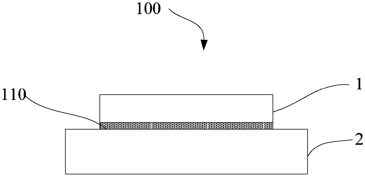
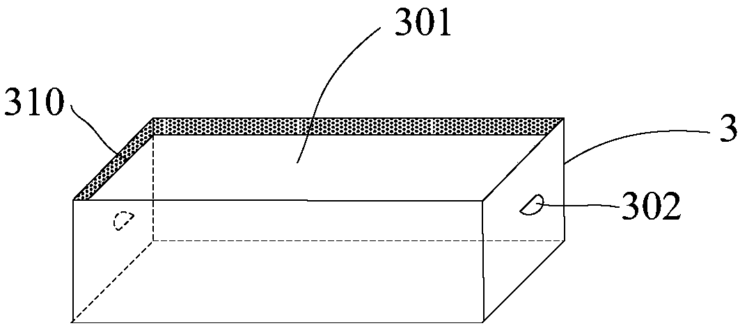
[0028] Figure 1 to Figure 3 It is a structural diagram corresponding to each step in the first embodiment of the manufacturing method of the target assembly of the present invention.

[0029] first reference figure 1 , providing a target assembly 100, the target assembly 100 includes a target 1 and a backing plate 2, and the target 1 is connected to the backing plate 2.

[0030] In this embodiment, the shape of the target 1 is a cuboid. In other embodiments, the shape of the target 1 may be a cylinder, an elliptical cylinder or other shapes.

[0031] In this embodiment, Velcro 110 is provided at the joint between the target 1 and the backboard 2 .

[0032] In other embodiments, double-sided adhesive tape and the like may also be provided at the joint between the target material 1 and the back plate 2 .

[0033] In this embodiment, adhesive tape is used to realize the bonding of the Velcro 110 and the target 1 . In other embodiments, glue and the like can be used to bond ...

no. 2 example

[0051] Figure 4 It is a structural schematic diagram of the set in the second embodiment of the manufacturing method of the target assembly of the present invention.

[0052] The difference between the second embodiment and the first embodiment is only that the set in the first embodiment is integrally formed, while the set in the second embodiment is formed step by step.

[0053] first reference Figure 4 , providing an inner sleeve 4, the side of the inner sleeve 4 is arranged in two layers.

[0054] In this embodiment, the inner sleeve 4 has an opening 401, and the inner sleeve 4 is also in the shape of a cuboid, which is due to figure 1 It is determined by the shape of the target material 1.

[0055] Taking one side of the inner sleeve 4 as an example, the two-layer structure of the side and the connection between the two layers are introduced.

[0056] In this embodiment, the sides include a first side 410 and a second side 420 .

[0057]In this embodiment, the fir...


PUM


Abstract

The invention provides a manufacturing method of a target material assembly. The method comprises the following steps of: providing the target material assembly, wherein the target material assembly comprises a target material and a back plate, and the target material is connected with the back plate; putting the target material into a sleeve; and carrying out sandblasting treatment to the back plate. The manufacturing method effectively realizes the shielding of the target material, and at the same time, the sleeve in shielding use can be reused, so the resource is saved, and the cost is saved.

Description

technical field [0001] The invention relates to the technical field of semiconductor manufacturing, in particular to a method for manufacturing a target component. Background technique [0002] In the semiconductor industry, a target assembly is composed of a target that meets the sputtering performance and a back plate that is combined with the target and has a certain strength. The back plate can play a supporting role when the target assembly is assembled to the sputtering base, and has the effect of conducting heat. [0003] Sand blasting the back plate is an important process in the processing of target components. Sand blasting is to use high-speed sand flow to impact the surface of the back plate, so that the surface of the back plate has a certain roughness, which is used to absorb anti-sputtering objects. If the roughness is too small, the adsorption effect is not strong, and the sputtered material will peel off and fall on the glass for the opposite LCD panel, whi...

Claims


Application Information

Patent Timeline
Patent Type & Authority Applications(China)
IPC IPC(8): C23C14/34
CPCC23C14/3407
Inventor 姚力军潘杰王学泽丁向前
Owner 合肥江丰电子材料有限公司
Learn More