Tail gas after-treatment mixing device

A technology of exhaust gas post-treatment and mixing device, which is applied in exhaust gas treatment, exhaust device, muffler device, etc., can solve the problems of low exhaust gas efficiency, low mixing uniformity, slow urea mixing rate, etc. The effect of speeding up efficiency and improving the degree of purification

Active Publication Date: 2022-06-21
宁波科森净化器制造有限公司
View PDF9 Cites 0 Cited by
  • Summary
  • Abstract
  • Description
  • Claims
  • Application Information

AI Technical Summary

Problems solved by technology

[0004]According to the above patent, the patent improves the mixing uniformity of exhaust gas and urea droplets by setting the swirl plate, and breaks the urea droplets by setting the distribution body The atomization and mixing effect of urea is improved. In addition, by setting the inner tube and outer tube, and forcing the airflow to flow in reverse through the end cap, the distance and time of urea evaporation are increased, and the uniformity of airflow mixing is improved. However, this patent only makes the mixing rate of urea and exhaust gas slow after being introduced through the effect of the swirl plate, the degree of uniformity of mixing is not high, and the efficiency of exhaust gas discharge is not high. A mixing device that is fully mixed with exhaust gas and can improve the efficiency of exhaust gas discharge

Method used


Image

  • Tail gas after-treatment mixing device
  • Tail gas after-treatment mixing device
  • Tail gas after-treatment mixing device

Examples


Embodiment Construction

[0045] In order to further understand the features, technical means, and specific objectives and functions of the present invention, the present invention will be described in further detail below with reference to the accompanying drawings and specific embodiments.

[0046] like Figure 1-Figure 12 As shown, this application provides:

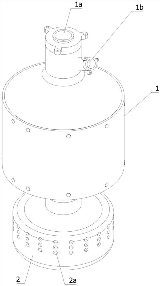
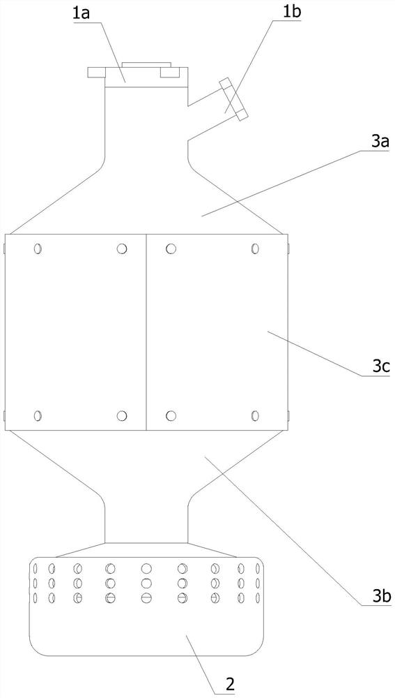
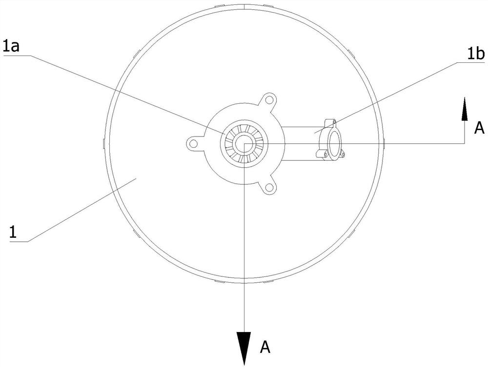
[0047] An exhaust gas post-processing mixing device, comprising a casing 1 and a gas-liquid mixing chamber 2 arranged at the lower end of the casing 1, the upper end of the casing 1 is provided with an intake connecting pipe 1a for the exhaust gas to enter the casing 1 and for urea to enter the casing. The nozzle 1b in the body 1 communicates between the gas-liquid mixing chamber 2 and the shell 1, the gas-liquid mixing chamber 2 is cylindrical, and the surface of the gas-liquid mixing chamber 2 is also provided with a number of nozzles for the discharge of harmless gases. Exhaust hole 2a, the shell 1 consists of an outer shell 3 and an inner...


PUM


Abstract

The invention relates to the field of tail gas aftertreatment, in particular to a tail gas aftertreatment mixing device which comprises a shell and a gas-liquid mixing chamber, a gas inlet connecting pipe and a nozzle are installed at the upper end of the shell, the gas-liquid mixing chamber is cylindrical, a plurality of exhaust holes are further formed in the surface of the gas-liquid mixing chamber, and the shell is composed of an outer shell and an inner shell; the inner shell is installed in the outer shell, the outer shell and the inner shell are the same in structure, the size of the outer shell is larger than that of the inner shell, a tail gas circulation cavity is formed in the inner shell, a urea circulation cavity is formed between the outer shell and the inner shell, and sufficient gas purification devices are further installed in the outer shell and the inner shell. The full gas purification device comprises an exhaust acceleration mechanism, a uniform mixing mechanism and a urea crushing mechanism, through the auxiliary mixing effect of the exhaust acceleration mechanism, the uniform mixing mechanism and the urea crushing mechanism on urea and tail gas, uniform mixing between the urea and the tail gas is achieved, the tail gas purification degree is improved, and the tail gas purification efficiency is improved. And the tail gas discharging efficiency is also improved.

Description

technical field [0001] The invention relates to the field of tail gas post-processing, in particular to a tail gas post-processing mixing device. Background technique [0002] Studies have shown that the uniformity of ammonia distribution in the pipeline of exhaust after-treatment systems (such as selective catalytic reduction systems, SCR systems) has an important impact on the overall performance and durability of the system. If the ammonia distribution is not uniform, it will lead to excessive ammonia in local areas. As a result, it is easy to cause ammonia leakage, and in other ammonia-lean areas, the conversion efficiency of nitrogen oxides (NOx) is too low, and the uneven distribution of ammonia for a long time will cause uneven aging of the catalyst, thereby affecting the overall performance of the catalyst. After the combustion chamber is discharged, the electric pump will inhale a sufficient amount of urea solution from the urea tank according to the instructions of...

Claims


Application Information

Patent Timeline
Patent Type & Authority Applications(China)
IPC IPC(8): F01N3/28
CPCF01N3/28F01N3/2892F01N2610/02F01N2610/14F01N2610/1453Y02T10/12
Inventor 钱旺木吕奎王宁
Owner 宁波科森净化器制造有限公司
Why Eureka
Try Eureka