
Detection circuit and detection method

A technology for detecting circuits and circuits, applied in the electronic field, can solve problems such as inability to locate devices, inaccurate test results of status registers, etc.

Active Publication Date: 2020-07-07
LOONGSON TECH CORP
View PDF12 Cites 0 Cited by
  • Summary
  • Abstract
  • Description
  • Claims
  • Application Information

AI Technical Summary

Problems solved by technology

However, this solution can only test the test results of the functions represented by the status register, and cannot locate the errors of specific devices, and the status register itself may be affected by radiation, making the test results inaccurate

Method used


Image

  • Detection circuit and detection method
  • Detection circuit and detection method
  • Detection circuit and detection method

Examples


Embodiment Construction

[0044] In order to make the above objects, features and advantages of the present invention more comprehensible, the present invention will be further described in detail below in conjunction with the accompanying drawings and specific embodiments.

[0045] One of the core concepts of the embodiments of the present invention is to design a detection circuit that can determine in real time whether a flip-flop error is a single event flip error, and can specifically locate the flip-flop where the error occurred.

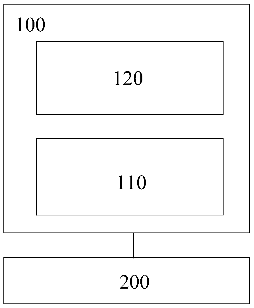
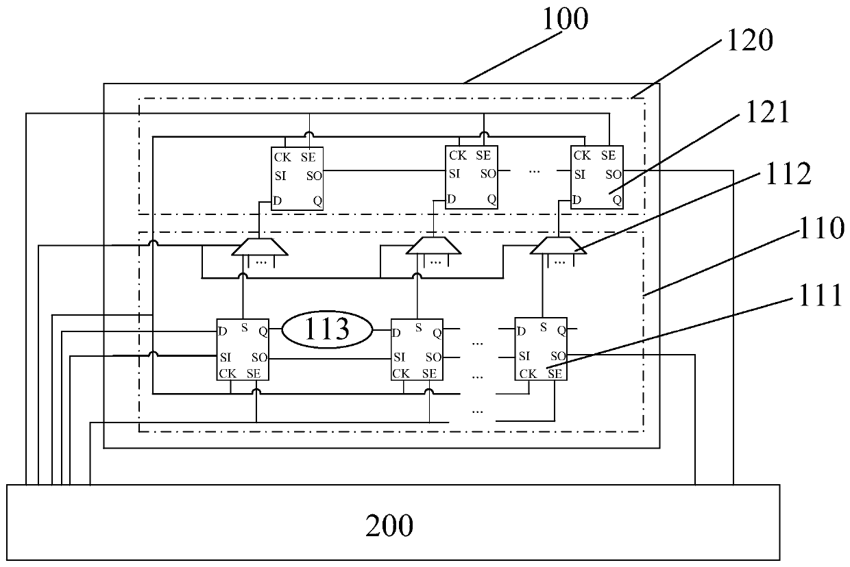
[0046] refer to figure 1 , shows a structural block diagram of Embodiment 1 of a detection circuit 100 of the present invention, the detection circuit 100 includes: a module under test 110 and a detection module 120, the module under test 100 has an inversion state output terminal and a data output terminal , the module under test 100 is connected to the detection module through the flip state output terminal, and the module under test is also connected to the preset d...


PUM


Abstract

The embodiment of the invention provides a detection circuit and a detection method. The detection circuit comprises a detected module and a detection module; the detected module is provided with an overturning state output end and a data output end; the detected module is connected with the detection module through the overturning state output end, and the detected module is further connected with a preset data processing device through the data output end; and the tested module is used for generating particle overturning state data and operation result data. According to the embodiment of the invention, whether the tested module has a storage error or not can be judged according to the matching condition of the particle overturning state data and the preset overturning reference data; and whether the tested module has a sampling error or not is judged according to the matching condition of the operation result data and preset logic reference data on the basis of judging whether the tested module has a storage error or not. Therefore, whether the data stored in the tested module have errors or not and the error type of the data are detected, and then the stability of the tested module under particle beam radiation is determined.

Description

technical field [0001] The invention relates to the field of electronic technology, in particular to a detection circuit and a detection method. Background technique [0002] The Single-Event Upsets effect refers to the jump of the potential state caused by a large number of high-energy charged particles in a digital circuit chip in a radiation environment, and "0" becomes "1", or "1" becomes "0". Phenomenon. In order to ensure the normal operation of aerospace equipment in orbit, use the ground high-energy proton or heavy ion radiation simulation equipment to conduct radiation tests on electronic components (including anti-single event flipping, single-event locking, and single-event burning capabilities), and as much as possible to test the internal components of the device. The single event flips the sensitive module for positioning, providing support for the subsequent radiation-resistant hardening design of the device. [0003] An existing irradiation test scheme is t...

Claims


Application Information

Patent Timeline
Patent Type & Authority Applications(China)
IPC IPC(8): G01R31/3177
CPCG01R31/3177
Inventor 刘延科杨梁范宝峡
Owner LOONGSON TECH CORP
Learn More