
Optical fiber combining device

An optical fiber and fiber slot technology, applied in the field of optical fiber communication, can solve the problems of ribbon fiber bubbles, bending, limited fiber length, etc.

Inactive Publication Date: 2020-07-07
SUZHOU JIALAN ZHIYUAN ELECTRONICS TECH CO LTD
View PDF6 Cites 0 Cited by
  • Summary
  • Abstract
  • Description
  • Claims
  • Application Information

AI Technical Summary

Problems solved by technology

[0003] Generally speaking, the number of standard ribbon optical fiber cores is 4 cores, 8 cores, and 12 cores. It is a ribbon optical cable made through a complex process of combining optical fibers. The initial production length is more than 1,000 meters, and our actual application process It is often encountered that it is necessary to combine multiple optical fibers within 1 meter or 2 meters, and after the fiber is completed, it needs to be welded to other products through a fusion splicer, so that the traditional process cannot realize the combination of optical fibers within a few meters.
In addition to the traditional process, there is also a similar device for paralleling fibers, but the paralleled ribbon fibers are prone to air bubbles, bending, glue residue, uneven thickness / width of the optical fiber ribbon, large fusion loss and limited length of the optical fiber for paralleling

Method used


Image

  • Optical fiber combining device
  • Optical fiber combining device

Examples


Embodiment Construction

[0022] The technical solutions in the embodiments of the present invention will be clearly and completely described below in conjunction with the accompanying drawings in the embodiments of the present invention. Obviously, the described embodiments are only part of the embodiments of the present invention, not all of them. Based on the implementation methods in the present invention, all other embodiments obtained by persons of ordinary skill in the art without making creative efforts belong to the protection scope of the present invention.

[0023] In the drawings, the shapes and dimensions may be exaggerated for clarity, and the same reference numerals will be used throughout to designate the same or like parts.

[0024] Unless otherwise defined, the technical terms or scientific terms used herein shall have the usual meanings understood by those skilled in the art to which the present invention belongs. "First", "second" and similar words used in the patent application spe...


PUM


Abstract

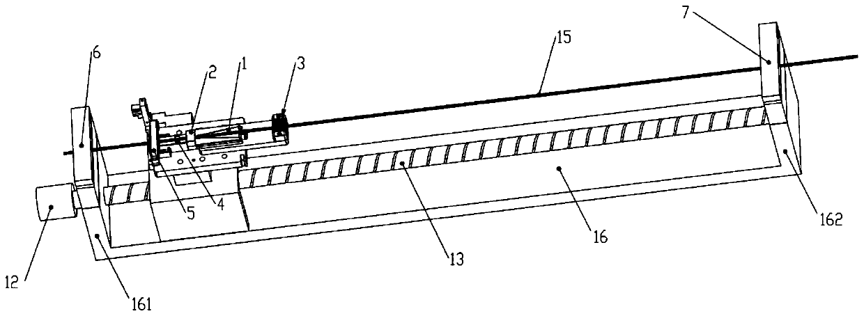
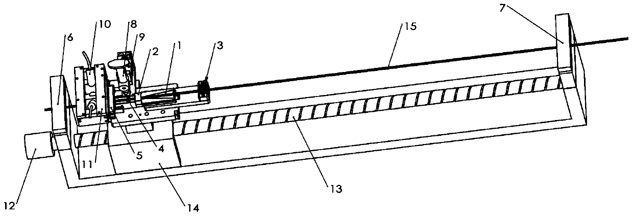
The invention discloses an optical fiber combining device. The device comprises an installation seat which is fixedly connected with a first base station and a second base station at intervals, a guide rail which is arranged between the first base station and the second base station, a dispensing table which is mounted on the guide rail in a sliding manner, and a driver which is used for driving the dispensing table to slide back and forth along the guide rail. The top surface of the dispensing table is provided with a downwards concave optical fiber accommodating groove, and the extending direction of the optical fiber accommodating groove is parallel to the extending direction of the guide rail. A glue groove is formed in the optical fiber accommodating groove in a communicated manner. The top of the first base station and the top of the second base station are rotationally connected with a first optical fiber fixing piece and a second optical fiber fixing piece respectively. According to the invention, the optical fiber accommodating groove capable of moving linearly is arranged, and a dispensed optical fiber bundle is cured while dispensing is carried out in the moving processof the optical fiber accommodating groove, so that the short-distance fiber combination of a plurality of optical fibers is realized.

Description

technical field [0001] The invention relates to the field of optical fiber communication, in particular to an optical fiber paralleling device. Background technique [0002] Optical fiber is referred to as optical fiber. Optical fiber is an optical waveguide structure composed of core and cladding. The propagation of light in the optical waveguide structure through total reflection has the characteristics of high speed, large capacity, and low loss. It is precisely because of these characteristics that optical fibers are It is widely used in the field of optical fiber communication. Usually, a single optical fiber can realize the reception and transmission of optical signals, and with the development of optical fiber communication, the requirements for transmission rate and transmission capacity are also increasing, which requires the use of multiple optical fibers for transmission or wavelength division The multiplexing method multiplexes the light of multiple optical fibe...

Claims


Application Information

Patent Timeline
Patent Type & Authority Applications(China)
IPC IPC(8): G02B6/255
CPCG02B6/255
Inventor 张佳伟魏军杰
Owner SUZHOU JIALAN ZHIYUAN ELECTRONICS TECH CO LTD
Learn More