welding equipment

A technology for welding equipment and connecting shafts, applied in welding equipment, metal processing equipment, welding/welding/cutting items, etc., can solve problems such as poor precision, uneven spot tin, and failure to meet welding requirements, etc., to achieve solder flatness, good welding quality

Active Publication Date: 2018-07-13
KUNSHAN XUNTAO PRECISION MACHINERY
View PDF8 Cites 0 Cited by
  • Summary
  • Abstract
  • Description
  • Claims
  • Application Information

AI Technical Summary

Problems solved by technology

[0002] With the wide application of tinning technology in electronic products, the requirements for tinning amount are strict. The traditional tinning method for electronic products is manual tinning, which is slow, difficult to control the amount of tin, and poor in precision, which is far from meeting the requirements of welding. It is easy to damage electronic products, the soldering is uneven and unsightly, manual handling is required after soldering, and the soldering quality is poor

Method used


Image

  • welding equipment
  • welding equipment
  • welding equipment

Examples


Embodiment Construction

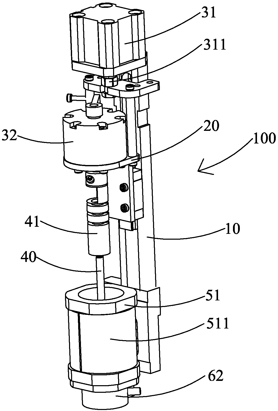
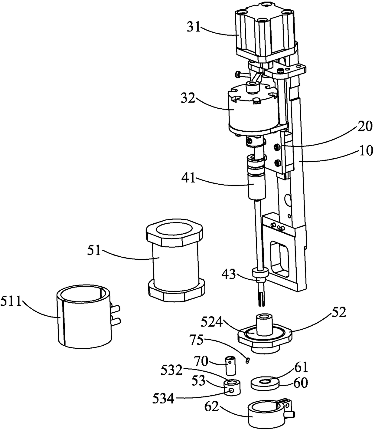
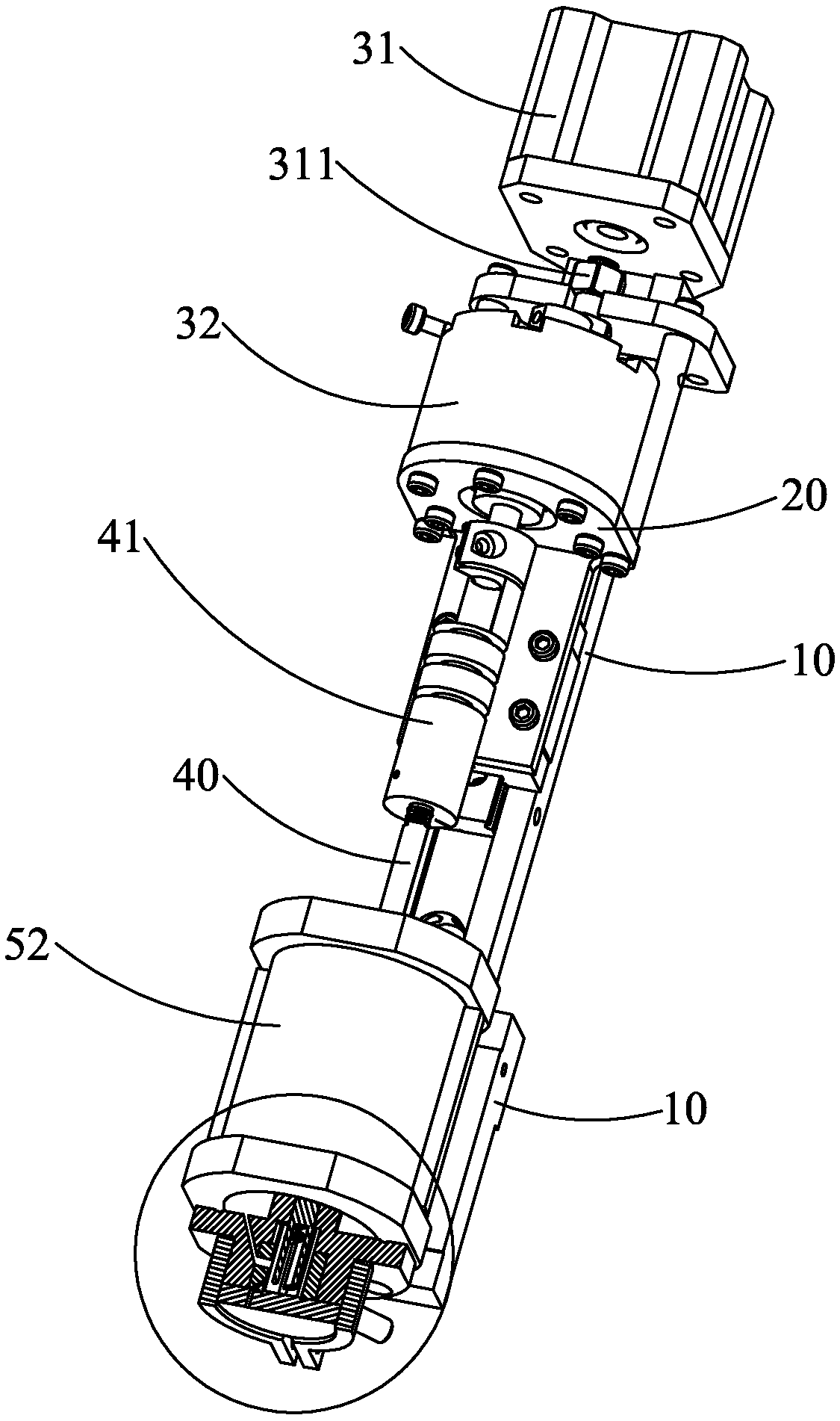
[0023] see Figure 1 to Figure 8 As shown, the welding equipment 100 of the present invention includes a frame 10, a sliding support 20, a displacement cylinder 31, a reversing cylinder 32, a plunger 40, an upper cavity 51, a lower cavity 52, an inner cavity 53, a base plate 60 and a rotating valve 70.

[0024] The frame 10 is set upright, and the sliding bracket 20 is slidably set on the frame 10 along the vertical direction. The displacement cylinder 31 is fixed on the frame 10 and is located above the sliding bracket 20. A displacement coupling shaft 311 is arranged between the two. The displacement cylinder 31 drives the sliding bracket 20 to move up and down through the displacement coupling shaft 311. The reversing cylinder 32 is fixed on the sliding bracket 20 and moves up and down following the sliding bracket 20 .

[0025] The plunger 40 is located below the reversing cylinder 32 , and a reversing coupling shaft 41 is connected between them, and the reversing cylind...


PUM


Abstract

The invention relates to a welding device which comprises a machine frame, a sliding support, a displacement cylinder, a steering cylinder, a plunger, an upper cavity, a lower cavity, an inner cavity, a bottom plate and a rotary valve. An upper containing cavity for containing liquid solder is arranged on the upper cavity. The inner cavity is contained in the lower cavity and provided with a lower containing cavity for containing liquid solder. A liquid inlet passageway for communicating the upper containing cavity with the lower containing cavity is arranged among the upper cavity, the lower cavity and the inner cavity. An ejecting passageway is arranged on the inner cavity. An ejecting hole penetrating downwards is formed in the bottom plate. The plunger extends into the lower containing cavity from the upper containing cavity. The rotary valve is contained in the lower containing cavity and arranged on the plunger in a sleeving mode to rotate along with the plunger. The rotary valve can alternatively block the outlet of the liquid inlet passageway in the rotating process. By means of the welding device, precise quantitative welding can be achieved.

Description

technical field [0001] The invention relates to the field of welding technology, in particular to a welding equipment adopting the principle of a plunger pump. Background technique [0002] With the wide application of tin spot technology in electronic products, the requirements for the amount of tin spot are strict. The traditional tin spot method for electronic products is manual tin spot, which is slow, difficult to control the amount of tin, and poor in precision, which is far from meeting the requirements of welding. It is easy to damage electronic products, and the soldering is uneven and unsightly. Manual processing is required after soldering, and the soldering quality is poor. Contents of the invention [0003] The object of the present invention is to provide a welding device capable of precise quantitative welding. [0004] In order to achieve the aforementioned purpose, the present invention adopts the following technical solutions: a welding equipment, which ...

Claims


Application Information

Patent Timeline
Patent Type & Authority Patents(China)
IPC IPC(8): B23K3/00B23K3/06B23K101/36
CPCB23K3/00B23K3/0607B23K2101/36
Inventor 顾福乾
Owner KUNSHAN XUNTAO PRECISION MACHINERY
Why Eureka
Try Eureka