Battery connection module

A battery connection and electrical connection technology, applied in the direction of batteries, secondary batteries, battery pack components, etc., can solve the problems of complex structure and instability

Active Publication Date: 2020-07-07
DONGGUAN MOLEX INTERCONNECT +1
View PDF11 Cites 5 Cited by
  • Summary
  • Abstract
  • Description
  • Claims
  • Application Information

AI Technical Summary

Problems solved by technology

Because the connection between the bus bar and the splint at the end of the battery module is through the adapter base, the three need to have a structure of mutual clamping and assembly, so the structure is more complicated and unstable

Method used


Image

  • Battery connection module
  • Battery connection module
  • Battery connection module

Examples


Embodiment Construction

[0193] Before the present invention is described in detail, it should be noted that in the following description, similar elements are denoted by the same numerals.

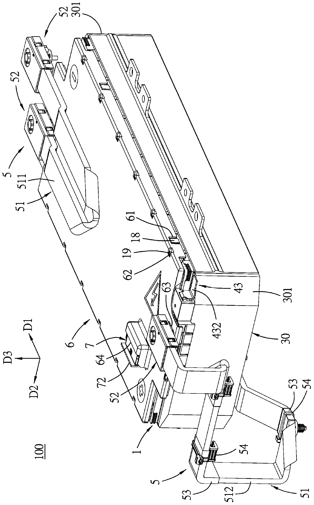
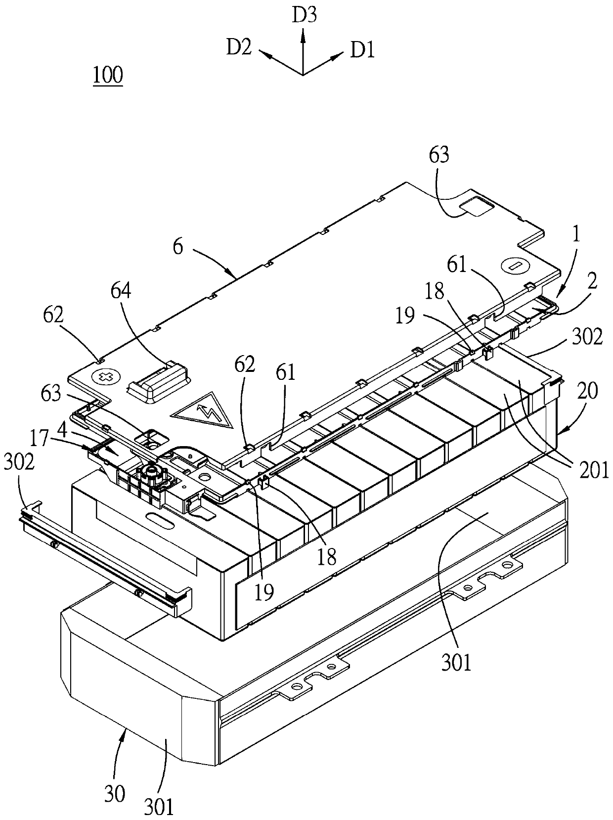
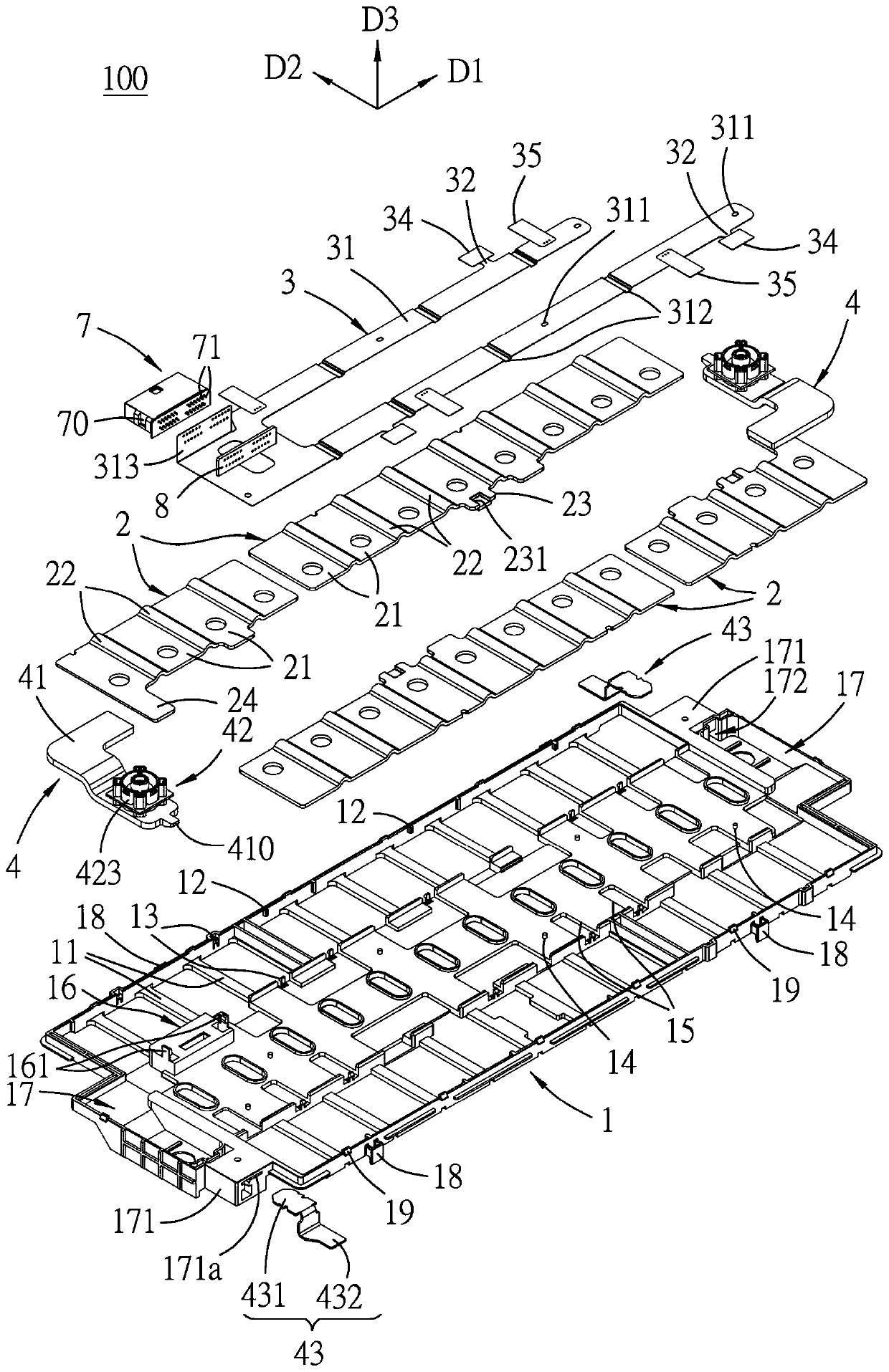
[0194] refer to Figure 1 to Figure 3 , a battery connection module 100 of a first embodiment proposed by the present invention is suitable for being electrically connected to a battery pack 20, the battery pack 20 has a plurality of batteries 201 (12 in the first embodiment) and The battery pack 20 is housed in a battery housing 30 together with the protective frames 302 disposed at the two ends, and the battery housing 30 has end plates 301 at two ends. The battery connection module 100 includes a carrier plate 1 , a plurality of busbars 2 , a flexible circuit board 3 , two electrode units 4 , two power connection bars 5 , and a top cover 6 .

[0195] The supporting tray 1 extends along a length direction D1 and is suitable for being disposed on the battery pack 20 , and is made of insulating material. The bu...


PUM


Abstract

A battery connection module comprises: a plurality of bus members, two bridging bus members, a flexible circuit board, an electrode unit and a power connection strip. Each bridging type bus member isprovided with a first bus section suitable for being electrically connected with a first battery pack, a second bus section suitable for being electrically connected with a second battery pack, and abridging section connected between the first bus section and the second bus section. The flexible circuit board comprises an extension arm and a temperature sensor arranged on the extension arm, and aconcave part for correspondingly accommodating the temperature sensor is formed in the bus member. The electrode unit comprises an electrode slice lapped on the bus member, an electrode slice holderfor holding the electrode slice, and a power connection seat arranged on the electrode slice. The electric power connecting strip is provided with an electric power connector which is in butt joint with the electric power connecting base through a buckling structure, an alignment structure, a fastener and a sleeve.

Description

technical field [0001] The invention relates to a battery connection module, in particular to a battery connection module for modularly connecting battery packs. Background technique [0002] US Patent No. US8,879,262 (corresponding to Chinese Patent Application No. CN201080048799.1) only discloses the structure of the folded confluence part of the confluence piece. [0003] Chinese utility model patent authorization announcement number CN206806468U discloses that the temperature sensor is installed on the busbar and fixed in a recess of a busbar. However, the temperature sensor and the circuit board need to be connected by additional wires or wires. Therefore, the structure and manufacture are relatively complicated, and the connection structure of the wire bonding is relatively easy to be damaged. [0004] Chinese Utility Model Patent Grant No. CN206742321U (corresponding to Chinese Patent Publication No. CN107046114A) discloses that the busbar is fixed on the splint at ...

Claims


Application Information

Patent Timeline
Patent Type & Authority Applications(China)
IPC IPC(8): H01M2/20H01M2/26H01M2/34H01M6/50H01M10/48H01M10/613H01M10/647H01M10/653H01M10/654H01M10/6554H01M50/209H01M50/505H01M50/51H01M50/516H01M50/522H01M50/531H01M50/586
CPCH01M50/507H01M50/503H01M50/519H01M50/569H01M50/296H01M50/298H01M50/505H01M50/516H01M50/543H01M50/50H01M50/204Y02E60/10H01M10/486H01M50/586H01M50/51H01M50/522H01M50/531H01M50/209H01M10/653H01M50/502
Inventor 林健兴吴筱凭洪丽琴章晓暖魏慧梅刘礼华
Owner DONGGUAN MOLEX INTERCONNECT
Why Eureka
Try Eureka