Piezoelectric ceramic driver clamping structure, linear driving device and periscopic lens

A piezoelectric ceramic and clamping structure technology, applied in the field of piezoelectric motors, can solve problems such as unavailability of side space

Pending Publication Date: 2020-07-07
NEW SHICOH MOTOR CO LTD
View PDF0 Cites 10 Cited by
  • Summary
  • Abstract
  • Description
  • Claims
  • Application Information

AI Technical Summary

Problems solved by technology

[0003] In the device driven by the piezoelectric ceramic driver, the piezoelectric ceramic driver is clamped by the metal shrapnel. In the existing structure, the upper shrapnel and the lower shrapnel are placed vertically at 90 degrees, and the upper shrapnel is on the side of the lower shrapnel, resulting in unusable side space.

Method used


Image

  • Piezoelectric ceramic driver clamping structure, linear driving device and periscopic lens
  • Piezoelectric ceramic driver clamping structure, linear driving device and periscopic lens
  • Piezoelectric ceramic driver clamping structure, linear driving device and periscopic lens

Examples


Embodiment 1

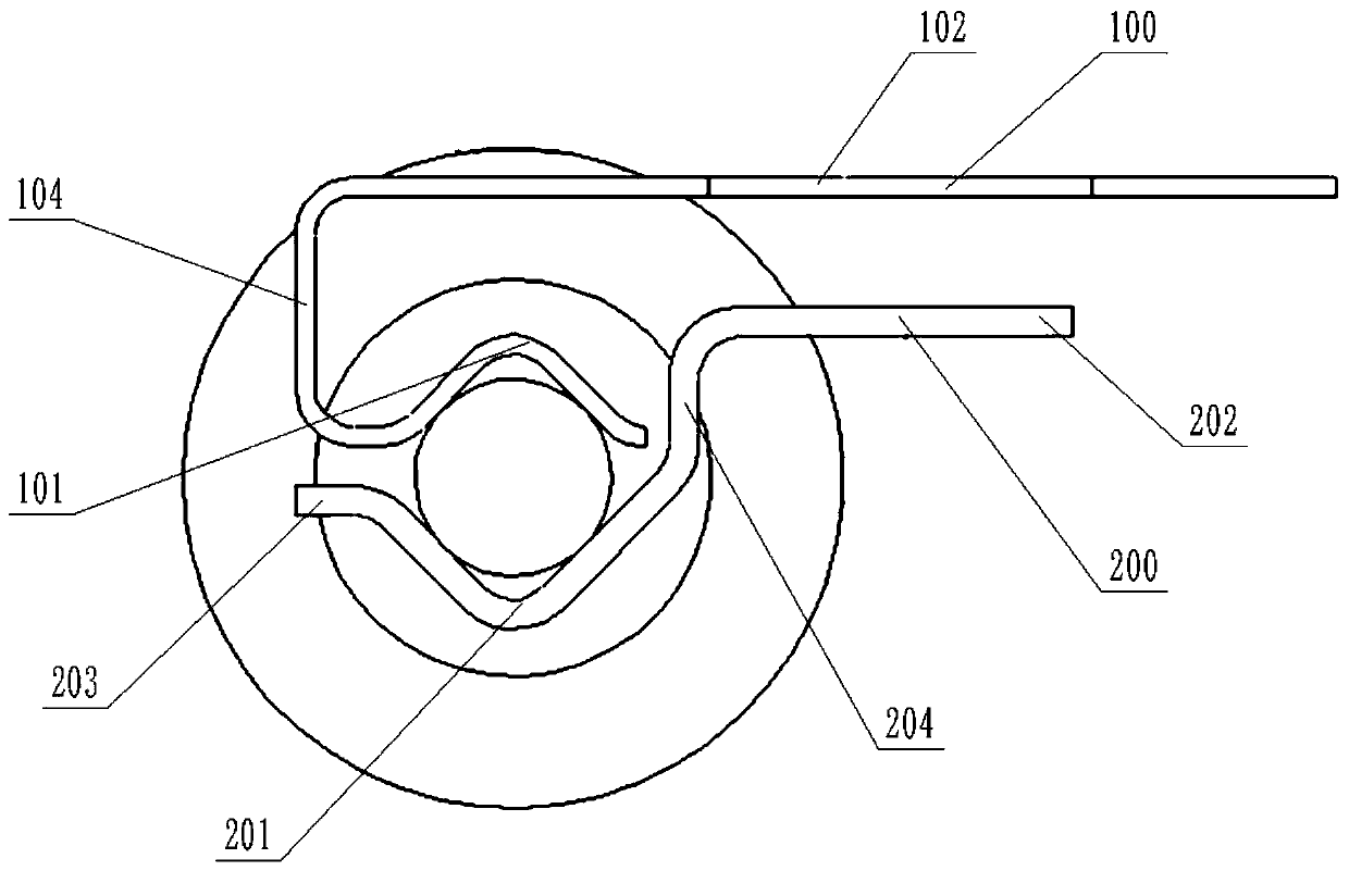
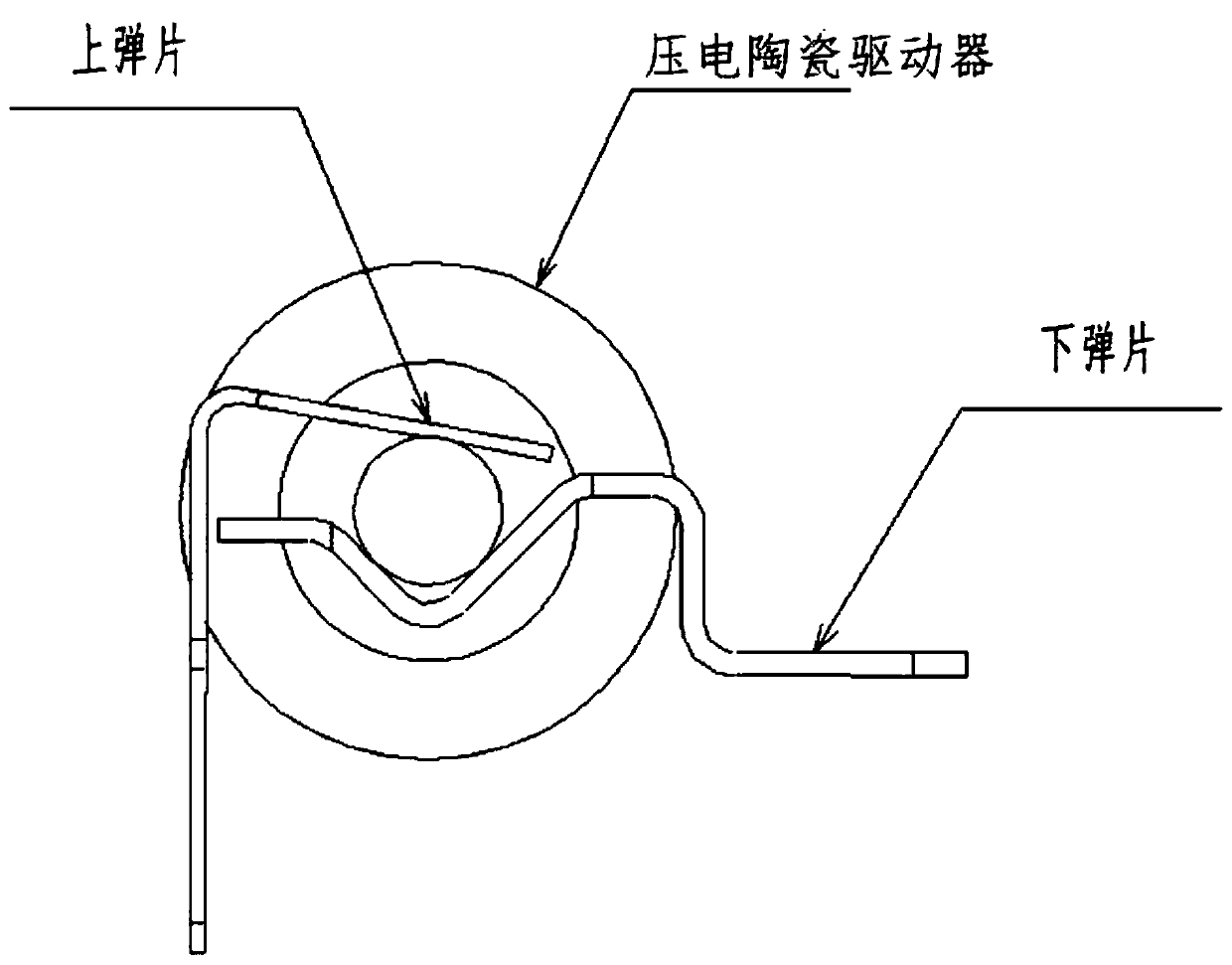
[0039] Example 1, please refer to Figure 1-4 , a clamping structure of a piezoelectric ceramic driver, comprising an upper elastic piece 100 and a lower elastic piece 200,

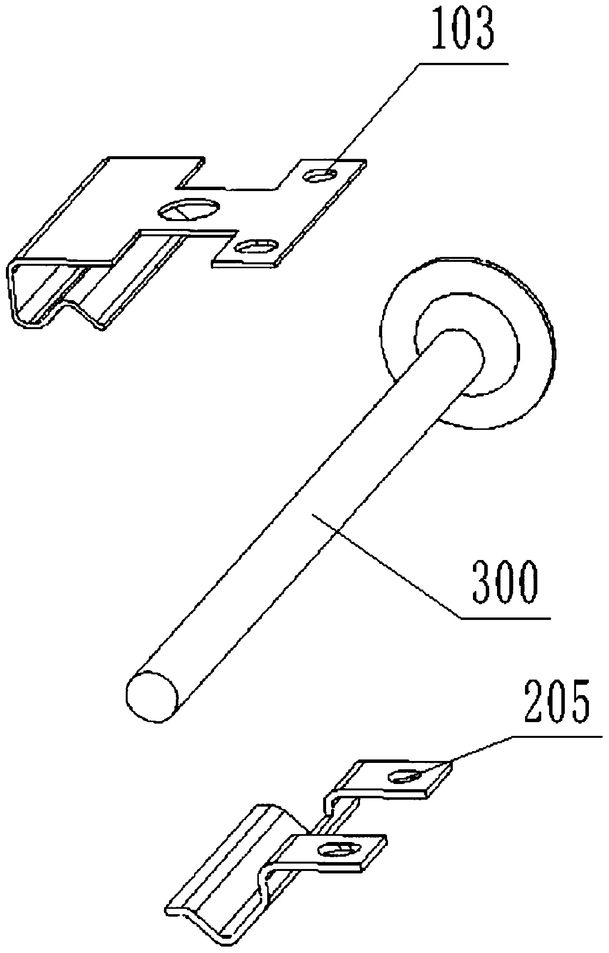
[0040] The upper elastic sheet 100 includes an integrally formed upper elastic sheet holding part 101 and an upper elastic sheet placement part 102. The upper elastic sheet placement part 102 is arranged horizontally, wherein the upper elastic sheet placement part 102 is in an I-shaped shape, and an upper installation hole is opened on the right side of the placement 103, the left end of the upper shrapnel placement part 102 is bent downward by 90 degrees to form an upper shrapnel vertical part 104, and the connection between the upper shrapnel placement part 102 and the upper shrapnel vertical part 104 is arranged in a circular arc transition, and the upper shrapnel vertical part 104 Bending 90 degrees to the right is connected with the upper elastic sheet holding part 101, and the connection between the...

Embodiment 2

[0045] Example 2, please refer to Figure 5-11 , a linear drive device, including the clamping structure of the above-mentioned piezoelectric ceramic driver, and also includes a frame body 400, a zoom lens bracket 500, a focusing lens bracket 600, a guide mechanism 700, and a piezoelectric ceramic driver 300;

[0046] The frame body 400 is a rectangular frame body with upper and lower openings, the upper and lower ends of the frame body 400 are provided with cover plates 401, and the cover plate 401 is fastened to the frame body 400;

[0047] Specifically, the left and right sides of the frame body are provided with fastening blocks 402, the left and right sides of the cover plate 401 are bent at 90 degrees, and the bent part is provided with a fastening groove adapted to the fastening block 402. 403;

[0048] The guide mechanism 700 is used to carry the zoom lens holder 500 and the focus lens holder 600 and make it slide on the guide mechanism 700. The guide mechanism 700 in...

Embodiment 3

[0058] Embodiment 3, the present invention also provides a periscope lens, including the linear drive device, and the periscope lens also includes a multi-reflection periscope ultra-telephoto structure, that is, by setting several The mirror structure is used to reflect multiple times to extend the optical path. Compared with the ordinary periscope lens, the optical path ratio is improved, and the telephoto is improved.

[0059] A telephoto lens has a long focal length, a small viewing angle, and a large image on the film. Therefore, at the same distance, it can shoot a larger image than the standard lens, which is very suitable for shooting distant objects. At the same time, because its depth of field is smaller than that of the standard lens, it can more effectively blur the background and highlight the focused subject. The subject and the camera are generally far apart, and the distortion in the perspective of the portrait is small, and the portrait will be more vivid. At t...


PUM


Abstract

The invention discloses a piezoelectric ceramic driver clamping structure, a linear driving device and a periscopic lens. The structure comprises an upper elastic piece and a lower elastic piece; theupper elastic piece comprises an upper elastic piece clamping part and an upper elastic piece placing part which are integrally formed; the upper elastic piece placing part is horizontally arranged, the upper elastic piece placing part is in an I shape, the left end of the upper elastic piece placing part is bent downwards by 90 degrees to form an upper elastic piece vertical part, and the upper elastic piece vertical part is bent rightwards by 90 degrees to be connected with the upper elastic piece clamping part; the upper elastic sheet does not occupy the side space. According to the invention, the periscopic lens is driven by the linear driving device, and the moving stroke is long; the optical axis of the lens is stable, the variation of the optical axis is small, no magnetic interference exists, the pushing force is large, a large-size lens can be pushed to improve the shooting quality, and a long stroke can be provided to support the focusing of a high-optical-magnification lens.

Description

technical field [0001] The invention relates to the field of piezoelectric motors, in particular to a piezoelectric ceramic drive clamping structure, a linear drive device and a periscope lens. Background technique [0002] Multi-camera mobile phones have become the standard configuration of smart phones. Due to the traditional design, the multi-camera design will limit the focal length of the mobile phone, making it difficult for the telephoto cam to zoom beyond 2 times. The periscope lens arranges the lenses horizontally, and with the help of special optical prisms, allows light to enter the lens group to achieve imaging. Such a design will not make the phone very thick, and more importantly, the periscope lens can make the image more stable. [0003] In the device driven by the piezoelectric ceramic driver, the piezoelectric ceramic driver is clamped by metal shrapnel. In the existing structure, the upper shrapnel and the lower shrapnel are placed vertically at 90 degree...

Claims


Application Information

Patent Timeline
Patent Type & Authority Applications(China)
IPC IPC(8): H02N2/00H02N2/04G02B7/04G03B13/34G03B17/17
CPCG02B7/04G03B13/34G03B17/17H02N2/005H02N2/006H02N2/04
Inventor 汪东明
Owner NEW SHICOH MOTOR CO LTD
Why Eureka
Try Eureka