Wireless charging receiving end load modulation switch zero-voltage asynchronous control method and circuit

A technology of load modulation and wireless charging, which is applied in the direction of electronic switches, circuits, circuit devices, etc., and can solve the problems of high voltage and current stress of load modulation switches, damage of load modulation switch tubes, etc.

Active Publication Date: 2020-07-07
CHENGDU YICHONG WIRELESS POWER TECH CO LTD
View PDF9 Cites 7 Cited by
  • Summary
  • Abstract
  • Description
  • Claims
  • Application Information

AI Technical Summary

Problems solved by technology

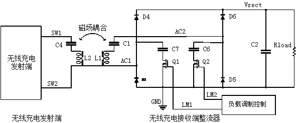
[0004] In the traditional control method of the load modulation switch, since AC1 (or AC2) is a rapidly changing alternating voltage, the switch tube Q1 and the switch tube Q2 are randomly turned on or off using the same control signal, which will inevitably cause the load modulation switch to bear more Large voltage and current stress, severe cases may lead to damage of the load modulation switch tube

Method used


Image

  • Wireless charging receiving end load modulation switch zero-voltage asynchronous control method and circuit
  • Wireless charging receiving end load modulation switch zero-voltage asynchronous control method and circuit
  • Wireless charging receiving end load modulation switch zero-voltage asynchronous control method and circuit

Examples


Embodiment Construction

[0022] In order to make the object, technical solution and advantages of the present invention clearer, the present invention will be further described in detail below in conjunction with the accompanying drawings and embodiments. It should be understood that the specific embodiments described here are only used to explain the present invention, and are not intended to limit the present invention, that is, the described embodiments are only some of the embodiments of the present invention, but not all of the embodiments. The components of the embodiments of the invention generally described and illustrated in the figures herein may be arranged and designed in a variety of different configurations. Accordingly, the following detailed description of the embodiments of the invention provided in the accompanying drawings is not intended to limit the scope of the claimed invention, but merely represents selected embodiments of the invention. Based on the embodiments of the present ...


PUM


Abstract

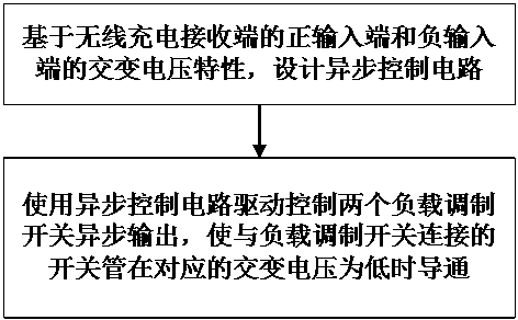
The invention discloses a wireless charging receiving end load modulation switch zero-voltage asynchronous control method and a wireless charging receiving end load modulation switch zero-voltage asynchronous control circuit. The wireless charging receiving end load modulation switch zero-voltage asynchronous control method comprises the steps of: designing an asynchronous control circuit based onalternating voltage characteristics of a positive input end and a negative input end of a wireless charging receiving end; and using the asynchronous control circuit to drive and control two load modulation switches for asynchronously output, so that switching tubes connected with the load modulation switches are conducted when the corresponding alternating voltage is low. According to the wireless charging receiving end load modulation switch zero-voltage asynchronous control method, the asynchronous control circuit is designed based on the alternating voltage characteristics of the positiveinput end and the negative input end of the wireless charging receiving end, when the load modulation switches are driven to be switched on, the corresponding alternating voltage is low, namely zerovoltage is turned on, the corresponding switch tubes are further turned on when the corresponding alternating voltage is low instead of being turned on immediately after a load modulation signal is ready, and the voltage and current stress of the load modulation switch tube can be effectively reduced.

Description

technical field [0001] The invention relates to the technical field of load modulation at a wireless charging receiving end, in particular to a zero-voltage asynchronous control method and circuit for a load modulation switch at a wireless charging receiving end. Background technique [0002] In the wireless charging system, the Wireless Charging Alliance has formulated a set of digital communication feedback methods from the wireless charging receiver to the wireless charging transmitter based on load modulation. The circuit diagram is shown in figure 1 shown. [0003] Among them, the load modulation switch composed of the switching tube Q1 and the switching tube Q2 connects or disconnects the capacitor C6 and the capacitor C7 through the switch signal modulated according to a certain coding rule, which causes the resonance parameter of L1-C1 to change. Through electromagnetic coupling, the The modulation information is transmitted to the wireless charging receiving end to...

Claims


Application Information

Patent Timeline
Patent Type & Authority Applications(China)
IPC IPC(8): H03K17/13H03K17/28H03K17/284H03K17/081H02J50/12
CPCH02J50/12H03K17/081H03K17/08104H03K17/13H03K17/133H03K17/28H03K17/284
Inventor 王建平黎杰王文戴义红李暾梁恩主
Owner CHENGDU YICHONG WIRELESS POWER TECH CO LTD
Why Eureka
Try Eureka