Multifunctional swivel chair tray and using method thereof

A multi-functional, swivel chair technology, applied in chairs, reclining chairs, applications, etc., can solve the problems of adjusting lifting, spring force, complex gear position, inability to slide and lock the bottom plate, unreasonable layout of the swivel chair tray, etc. , to avoid sedentary discomfort, the effect of high integration

Active Publication Date: 2020-07-10
HANGZHOU ZHONGTAI IND GRP
View PDF12 Cites 6 Cited by
  • Summary
  • Abstract
  • Description
  • Claims
  • Application Information

AI Technical Summary

Problems solved by technology

[0003] The present invention provides a multi-functional swivel chair tray and its use method, which mainly solves the problems in the prior art that the swivel chair tray has less functions, the adjustment of lifting, spring force, and gear position is relatively complicated, and the bottom plate cannot slide And locking, poor integration, unreasonable layout of the swivel chair tray, large volume and other technical problems

Method used


Image

  • Multifunctional swivel chair tray and using method thereof
  • Multifunctional swivel chair tray and using method thereof
  • Multifunctional swivel chair tray and using method thereof

Examples


Embodiment 1

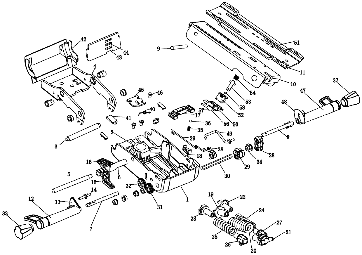
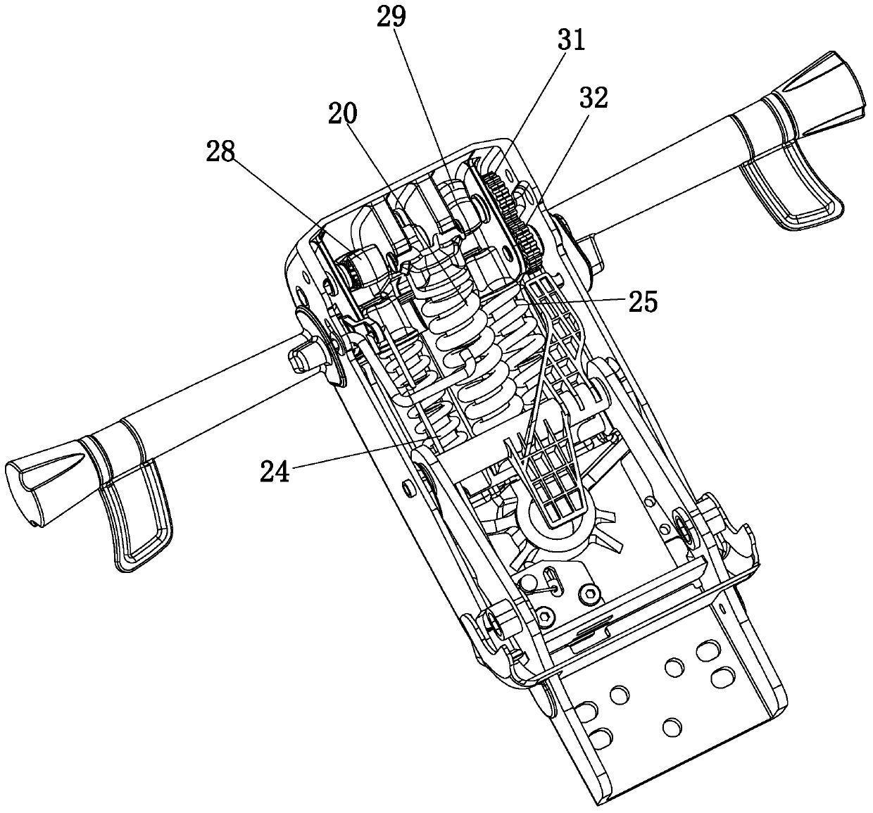
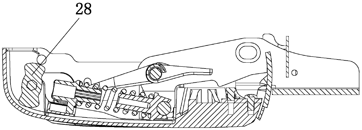
[0041] Embodiment 1: A kind of multifunctional swivel chair tray, such as figure 1 , including a main body 1, the main body is provided with a lifting rod connecting hole 2, the main body is connected to the seesaw 4 through the second rotating shaft 5, and the second rotating shaft is connected with a lifting block 6, the lifting block is located above the connecting hole of the lifting rod, and the lifting block is connected with Lifting drive mechanism, one side of the main body is connected with a first adjustment rod 7, the first adjustment rod is connected with a multi-spring group adjustment mechanism, the other side of the main body is provided with a second adjustment rod 8, and the second adjustment rod is connected with gear adjustment Mechanism, the seesaw is connected with the base plate 10 through the third rotating shaft 9, the first rotating shaft 3 is connected between the base plate and the seesaw, the slide plate 11 is slidably connected on the base plate, an...

Embodiment 2

[0055] Embodiment 2: a kind of multifunctional swivel chair tray, such as Figure 10 , Figure 11 , Figure 12 , its structure is similar to that of Embodiment 1, the main difference is that the main body in this embodiment is connected with a connecting seat 100, the connecting hole of the lifting rod runs through the upper and lower ends of the connecting seat, and the upper end of the connecting seat is provided with a universal ball head 101, the main body There is a spherical slot 102 on the top, and the universal ball head can be universally rotated and installed in the spherical slot hole. The outer wall of the universal ball head is provided with a circle of guide grooves 103 evenly distributed in the circumferential direction, and the guide groove is in the shape of a concave arc. Curved surface structure, several massage mechanisms are evenly distributed on the main body. The massage mechanism includes push rod 104, connecting rod 105, lifting guide groove 106, slid...


PUM


Abstract

The invention relates to a swivel chair tray, in particular to a multifunctional swivel chair tray and a using method thereof. The technical problems that in the prior art, a swivel chair tray is fewin function, lifting, spring force and gears are complex to adjust, a bottom plate cannot slide and be locked, the integration degree is poor, the layout of the swivel chair tray is unreasonable, andthe size is large are mainly solved. The multifunctional swivel chair tray comprises a main body; the main body is connected with a warping plate through a second rotating shaft; a lifting block penetrates through the second rotating shaft; the lifting block is connected with a lifting driving mechanism; a first adjusting rod is connected to one side of the main body in a penetrating mode and connected with a multi-spring grouping adjusting mechanism; a second adjusting rod is arranged on the other side of the main body and connected with a gear adjusting mechanism; the warping plate is connected with a bottom plate through a third rotating shaft; a sliding plate is slidably connected to the bottom plate; and a sliding plate locking mechanism is arranged between the bottom plate and the sliding plate.

Description

technical field [0001] The invention relates to a swivel chair tray, in particular to a multi-functional swivel chair tray and a usage method thereof. Background technique [0002] The currently known swivel chair tray consists of an upper tray, a lower joist, a fulcrum, and spring device components. After the upper tray is fixed to the back of the swivel chair seat, the swivel chair can be properly pitched around the fulcrum to make the user feel comfortable. The Chinese patent discloses a tray (publication number: CN 2587252Y), which mainly includes a bottom plate, a movable seat, a tapered tube, and an adjustment device. The movable seat is fixedly connected to the bottom plate, and a tapered tube is arranged on the other side of the movable seat The fixed plate, the tapered tube fixed plate and the movable seat and the conical tube are fixedly connected; the adjusting device includes an adjusting rod, an adjusting plate, a torsion spring, and a torsion spring fixing plat...

Claims


Application Information

Patent Timeline
Patent Type & Authority Applications(China)
IPC IPC(8): A47C7/00A47C3/18A61H7/00
CPCA47C7/00A47C3/18A61H7/001A61H2201/0149A61H2205/086A61H1/00A61H2205/088A61H2203/0431A61H23/006A61H2201/1633A47C1/03238A47C1/03255A47C1/03272A47C1/03266A47C1/03274A47C3/30
Inventor 倪永兴
Owner HANGZHOU ZHONGTAI IND GRP
Why Eureka
Try Eureka