
Powder box of beverage machine

A beverage machine and powder box technology, which is applied in beverage preparation devices, household appliances, applications, etc., can solve the problems that powder materials are easily damped, affect accuracy and efficiency, and flocculate, so as to ensure food hygiene and reduce setting time. , Improve the effect of powder output accuracy

Pending Publication Date: 2020-07-10
CHANGZHOU PILOT ELECTRONICS
View PDF1 Cites 1 Cited by
  • Summary
  • Abstract
  • Description
  • Claims
  • Application Information

AI Technical Summary

Problems solved by technology

[0003] Chinese Patent Authorization Notice No. CN209331798U discloses a beverage machine capable of preventing material from falling out of the outlet. After the beverage machine feeds the powder, the pusher rod is reversed so that the powder leaves the outlet to prevent the powder from falling. The disadvantages are: 1. The powder outlet is always open, and the powder is easily affected by moisture and lint, which affects the taste of the beverage and even causes serious hygiene problems; At the powder outlet, the powder pusher rod needs to be reversed several times, which affects the accuracy and efficiency of the next powder discharge; 3. To improve the powder discharge accuracy and efficiency, a high requirement is put forward for the electronic control device that controls the powder pusher rod. Require
[0004] There are still some beverage machines on the market, which have a powder outlet that can be closed and can be opened and closed manually, but there will be cases where the opening and closing are forgotten. In addition to the problem of moisture, the powder is easy to float to the main machine, which is unhygienic

Method used


Image

  • Powder box of beverage machine
  • Powder box of beverage machine
  • Powder box of beverage machine

Examples


Embodiment Construction

[0034] The present invention will now be further described in conjunction with the accompanying drawings and preferred embodiments. These accompanying drawings are all simplified schematic diagrams, and only illustrate the basic structure of the present invention in a schematic manner, so they only show the configurations related to the present invention.

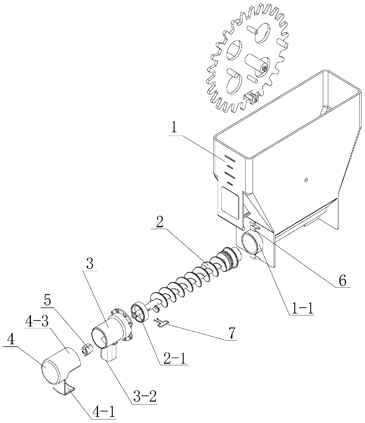
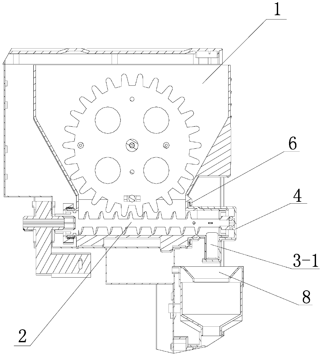
[0035] combine figure 1 and figure 2 A beverage machine powder box, which has a box body 1, a horizontal screw pusher rod 2 with a front end protruding from the box body 1 is provided at the bottom of the cavity of the box body 1, and the outer wall of the box body 1 where the front end of the screw pusher rod 2 protrudes There is a powder outlet cabin 3 on the top, and the front end of the screw pusher rod 2 is supported on the powder outlet cabin 3. The screw pusher rod 2 also has an extension section 2-1 protruding from the powder outlet cabin 3, and the extension section 2-1 is provided with hatch 4;

[0036] The pow...


PUM


Abstract

The invention relates to the technical field of beverage machines, in particular to a powder box of a beverage machine. The problem that an existing powder box is prone to damp is mainly solved. According to the scheme, the powder box comprises a box body and a spiral powder pushing rod, a powder outlet cabin is arranged on the outer wall of the box body at the extending part of the front end of the spiral powder pushing rod; the front end of the spiral powder pushing rod is supported on the powder outlet cabin; the spiral powder pushing rod is also provided with an extension section extendingout of the powder outlet cabin; a cabin door is arranged on the extending section, the powder outlet bin is provided with a material channel extending downwards and a material opening in the lowermost end of the material channel. The cabin door is provided with a cabin cover for opening the material opening when the cabin door forwards rotates along with the spiral powder pushing rod and blockingthe material opening when the cabin door reversely rotates along with the spiral powder pushing rod; and a structure for stopping the cabin door from rotating even after the cabin door forwards rotates to open the material opening and the cabin door reversely rotates to close the material opening is arranged between the cabin door and the powder outlet cabin.

Description

technical field [0001] The invention relates to the technical field of beverage machines, in particular to a powder box used in the beverage machine. Background technique [0002] There are more and more types of beverage machines, such as coffee machines, soybean milk machines and various mixed beverage machines. There are also more and more types of solid powder used in beverage machines. These powders are usually easy to be affected by moisture. It is necessary to ensure smooth powder feeding and Accurate and quantitative powder feeding makes the powder box for storing and sending out solid powder a key part of the beverage machine. [0003] Chinese Patent Authorization Notice No. CN209331798U discloses a beverage machine capable of preventing material from falling out of the outlet. After the beverage machine feeds the powder, the pusher rod is reversed so that the powder leaves the outlet to prevent the powder from falling. The disadvantages are: 1. The powder outlet i...

Claims


Application Information

Patent Timeline
Patent Type & Authority Applications(China)
IPC IPC(8): A47J31/40
CPCA47J31/404
Inventor 周利
Owner CHANGZHOU PILOT ELECTRONICS
Learn More