Wheel-leg composite type robot moving device and wheel-leg composite type robot

A mobile device and composite technology, applied in the field of robots, can solve the problem of a large number of joints in a wheel-leg mobile device, and achieve the effects of fast and convenient mode switching, simple control, and improved structural strength

Active Publication Date: 2020-07-10
SHANGHAI AEROSPACE SYST ENG INST
View PDF7 Cites 5 Cited by
  • Summary
  • Abstract
  • Description
  • Claims
  • Application Information

AI Technical Summary

Problems solved by technology

[0004] The object of the present invention is to provide a wheel-leg compound robot moving device and a wheel-leg compound robot to solve the problem of the large number of joints in the wheel-leg moving device in the prior art

Method used


Image

  • Wheel-leg composite type robot moving device and wheel-leg composite type robot
  • Wheel-leg composite type robot moving device and wheel-leg composite type robot
  • Wheel-leg composite type robot moving device and wheel-leg composite type robot

Examples


Embodiment 1

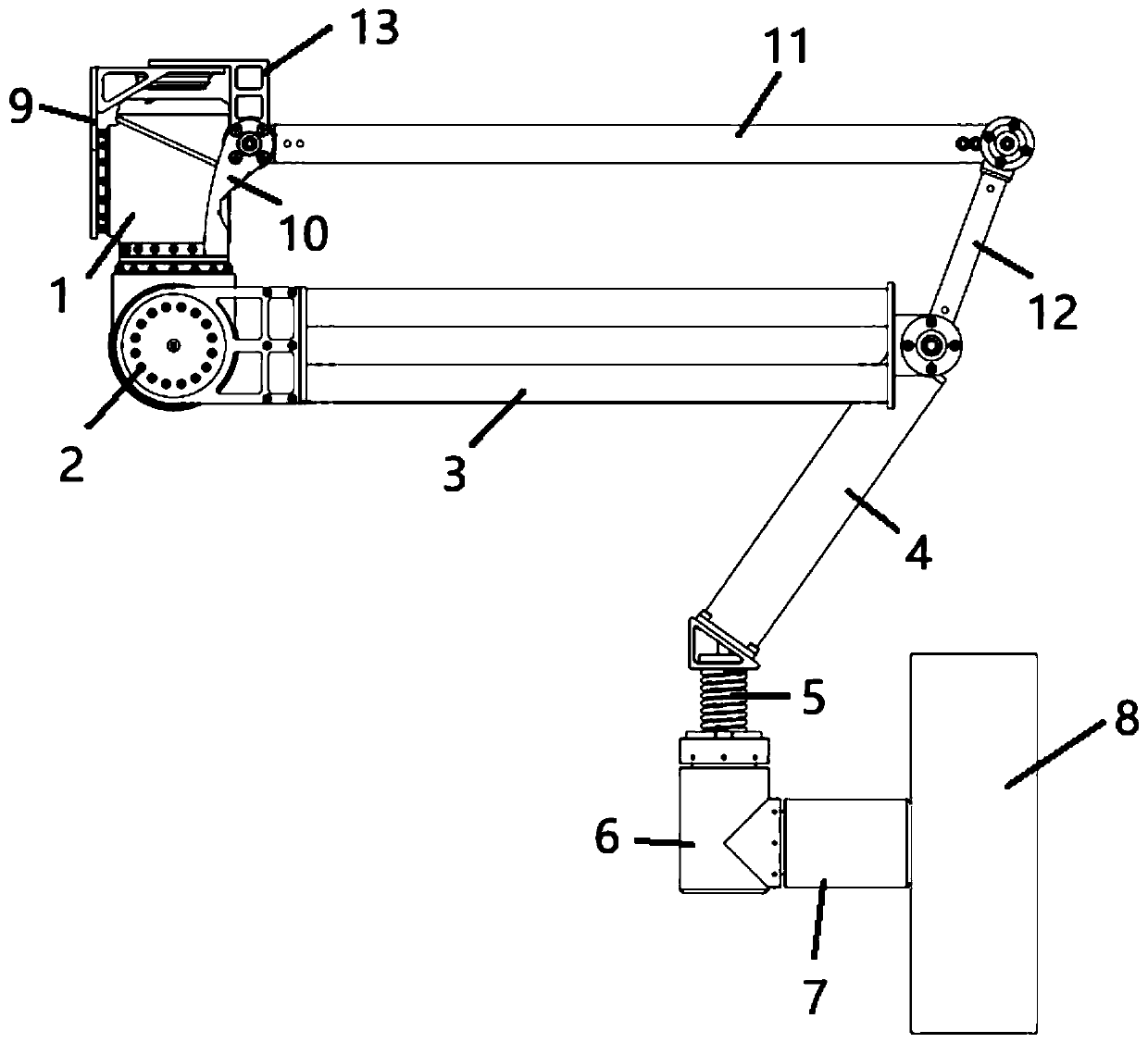
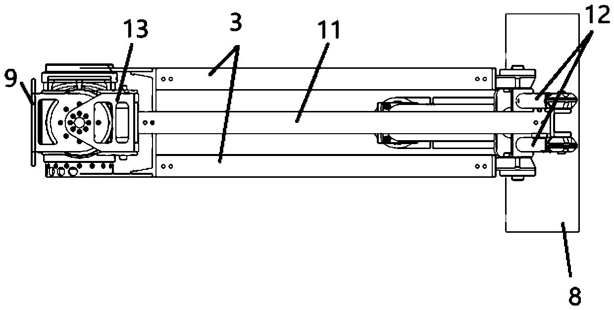
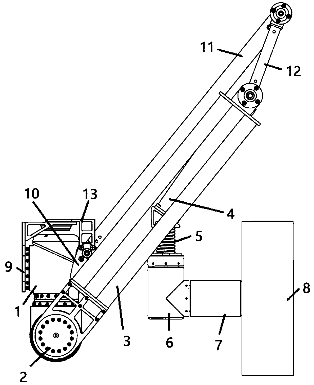
[0058] see Figure 1 to Figure 4 , the present embodiment provides a wheel-leg compound robot mobile device, comprising a hip joint, a hip joint driver, a leg comprising at least one first rod 3 and at least one second rod 4, an ankle joint driver, a wheel Drives and wheels 8. The hip joint part comprises the hip joint driver and the installation part 9 for connecting the robot body 14, the hip joint driver is connected with the installation part 9; the output end of the hip joint driver is connected with the hip joint driver, and the hip joint driver is used for The hip joint driver is driven to rotate around the axis of the output end of the hip joint driver. The output end of the hip joint driving part is connected with the first end of the first rod 3, and the hip joint driving part is used to drive the first rod 3 to rotate around the axis of the output end of the hip joint driving part. The second end of the first rod 3 is rotatably connected with the first end of the ...

Embodiment 2

[0073] see Figure 1 to Figure 3 , this embodiment provides a wheel-leg compound robot mobile device, on the basis of Embodiment 1, the legs are improved.

[0074] On the basis of Embodiment 1, the legs further include at least one support rod 10 , at least one parallel rod 11 and at least one connecting rod 12 . One end of the support rod 10 is connected to the hip joint driver, and the other end is rotatably connected to the first end of the parallel rod 11 . One end of the connecting rod 12 is connected with the first end of the second rod 4, and the other end is rotatably connected with the second end of the parallel rod 11; connect. The support rod 10 and the hip joint driver form a parallelogram four-bar linkage together with the first rod 3 , the connecting rod 12 and the parallel rod 11 .

[0075] Specifically, the above-mentioned rotational connections can all be connected through bearings. The support rod 10 and the hip joint motor 2 together with the first rod 3...

Embodiment 3

[0081] see Figure 5 to Figure 7 , this embodiment provides a wheel-leg compound robot, which is equipped with any one of the wheel-leg compound robot moving devices in Embodiment 1 or Embodiment 2 through the mounting member 9 .

[0082] 4, 6 or 8 wheel-leg compound mobile devices can be selected on each wheel-leg compound robot. The wheel-leg compound robot can realize leg-type multi-gait movement, wheel-type movement and wheel-leg Compound sports, with efficient mobility and ability to pass through complex terrain.

[0083] The wheel-leg compound robot provided in this embodiment is equipped with six wheel-leg compound robot moving devices evenly distributed on the peripheral side of the body 14 . When the wheel-leg compound robot is performing wheeled motion, the wheels 8 in the 6 wheel-leg compound robot moving devices all contact the traveling surface (such as the ground, the surface of the moon, etc.), and the 6 wheels advance toward a square simultaneously. When the ...


PUM


Abstract

The invention discloses a wheel-leg composite type robot moving device and a wheel-leg composite type robot. The wheel-leg composite type robot moving device comprises an installation part used for being connected with a robot body, a crotch joint driving part, a hip joint driving part, a first rod, a second rod, an ankle joint driving part, a wheel driving part and wheels, wherein the crotch joint driving part, the hip joint driving part, the first rod, the second rod, the ankle joint driving part, the wheel driving part and the wheels are connected successively in series. The second rod andthe ankle joint driving part are in fixed connection and other parts are in rotating connection. The installation part is connected with the crotch joint driving part. The crotch joint driving part isused for driving the hip joint driving part to rotate around the axis of the output end of the crotch joint driving part. The hip joint driving piece is used for driving the first rod to rotate around the axis of the output end of the hip joint driving piece. The ankle joint driving piece is used for driving the ankle joint driving piece to rotate around the axis of the output end of the ankle joint driving piece. The wheel driving piece is used for driving the wheel to rotate around a rotating shaft of the wheel. Compared with a traditional wheel leg type moving device, the wheel-leg composite type robot moving device has advantages that the number of joints is smaller, and control is simpler.

Description

technical field [0001] The invention belongs to the technical field of robots, and in particular relates to a wheel-leg compound robot moving device and a wheel-leg compound robot. Background technique [0002] The main moving modes of the robot are wheeled, legged, crawler, wheel-legged, and bouncing. For deep-space exploration robots, the wheel-type movement has weak ability to overcome obstacles; the leg-type robot consumes too much energy and has low efficiency; the crawler-type structure is too high-quality, which is not suitable for deep-space exploration; the bounce-type robot has poor controllability. The wheel-leg mobile device takes into account the characteristics of high-efficiency wheel-type movement and strong obstacle-surmounting ability of the leg type, and is the preferred mobile solution for future deep space exploration robots. [0003] At present, the wheel-legged mobile device needs to realize two modes of movement and mode switching, so there will be p...

Claims


Application Information

Patent Timeline
Patent Type & Authority Applications(China)
IPC IPC(8): B62D57/028
CPCB62D57/028
Inventor 陈超云韩亮亮杨健谷程鹏张文奇陈萌施飞舟张玉花
Owner SHANGHAI AEROSPACE SYST ENG INST
Why Eureka
Try Eureka