Power generation system for recycling waste heat of compressed gas

A waste heat recovery and compressed gas technology, applied in liquid fuel engines, engine components, machines/engines, etc., can solve the problems of increased power consumption, high production cost of compressed gas, energy waste, etc., to avoid waste, achieve good recovery effect, The effect of reducing production costs

Active Publication Date: 2020-07-10
董荣华
View PDF4 Cites 1 Cited by
  • Summary
  • Abstract
  • Description
  • Claims
  • Application Information

AI Technical Summary

Problems solved by technology

Therefore, the heat energy in the process of compressed gas production is finally dissipated into the atmosphere, which causes a waste of energy, and the circulation of cooling water in water cooling will also increase the consumption of electric energy, and the production cost of compressed gas is high.

Method used


Image

  • Power generation system for recycling waste heat of compressed gas
  • Power generation system for recycling waste heat of compressed gas
  • Power generation system for recycling waste heat of compressed gas

Examples


Embodiment Construction

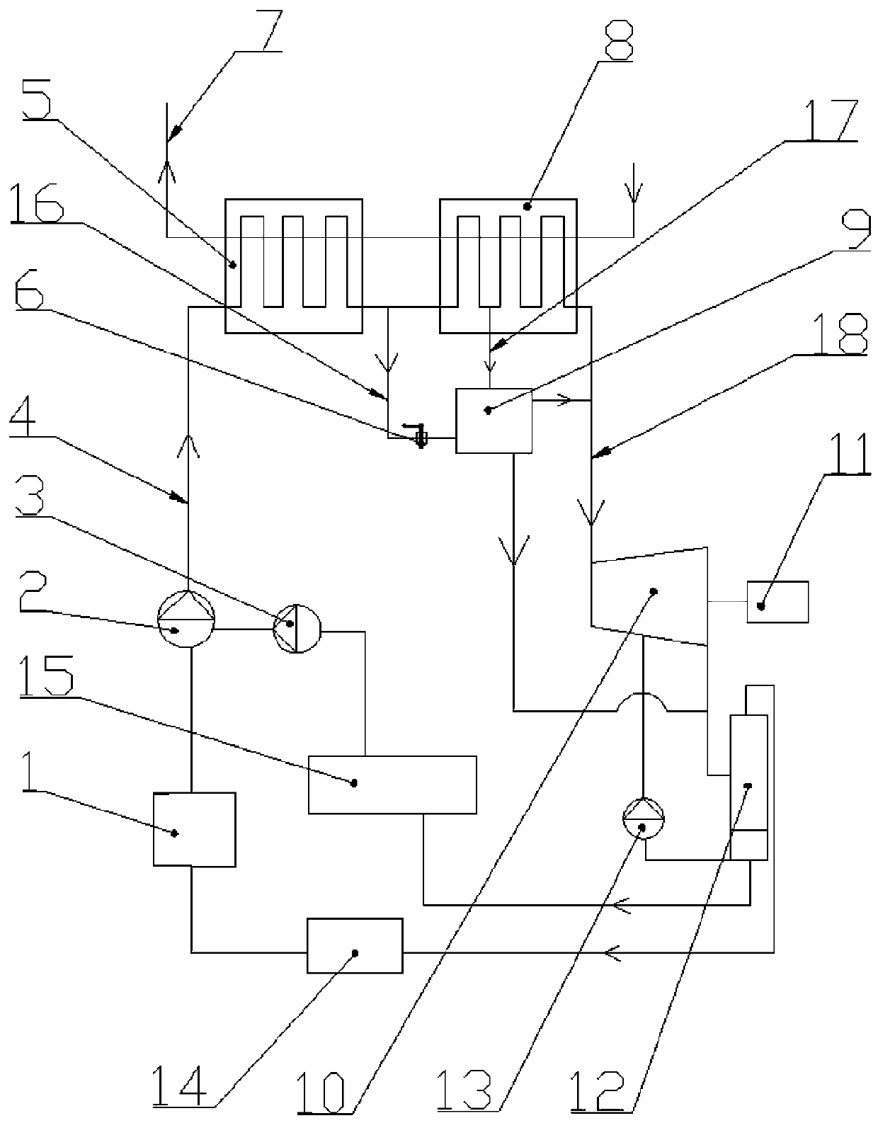
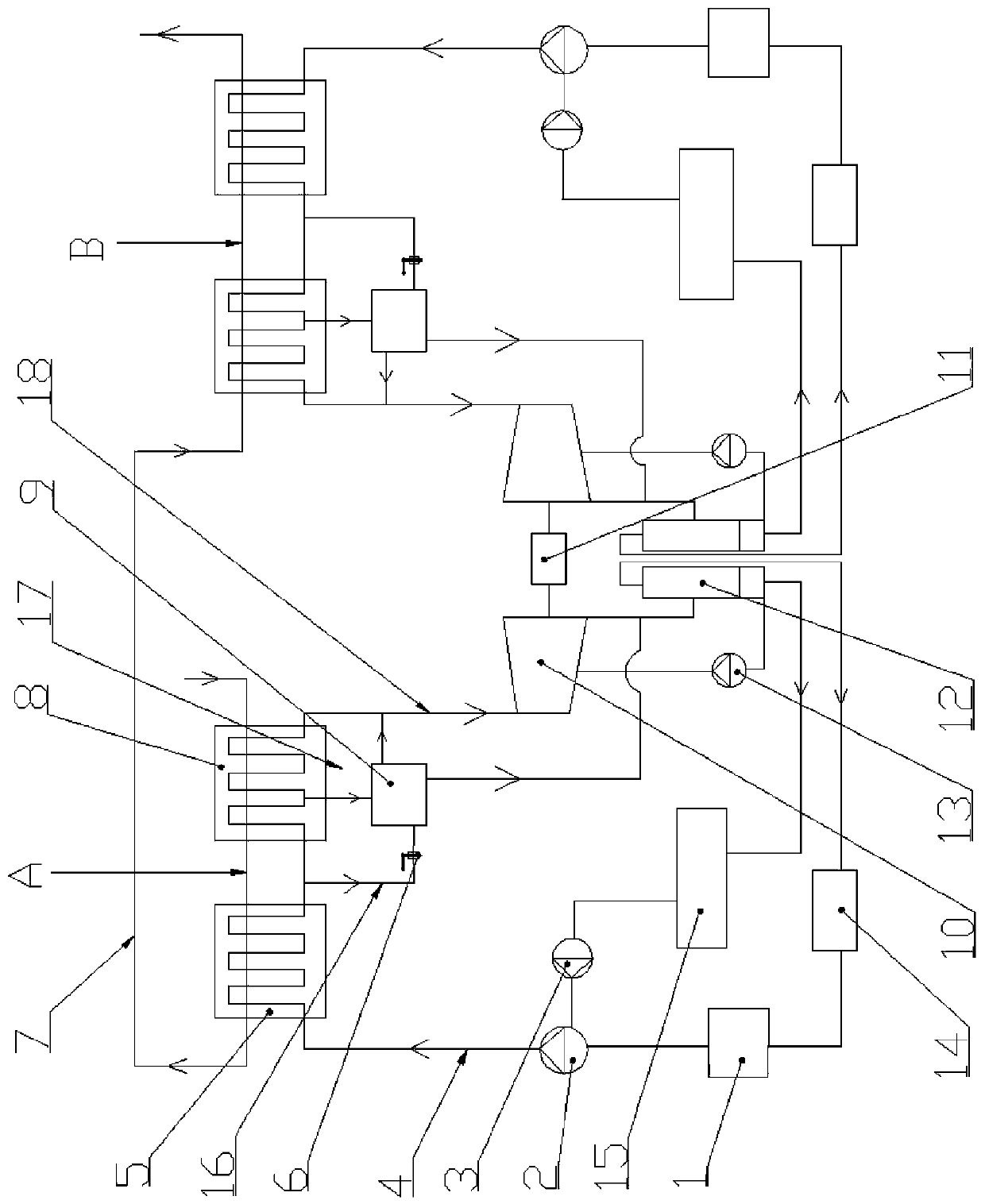
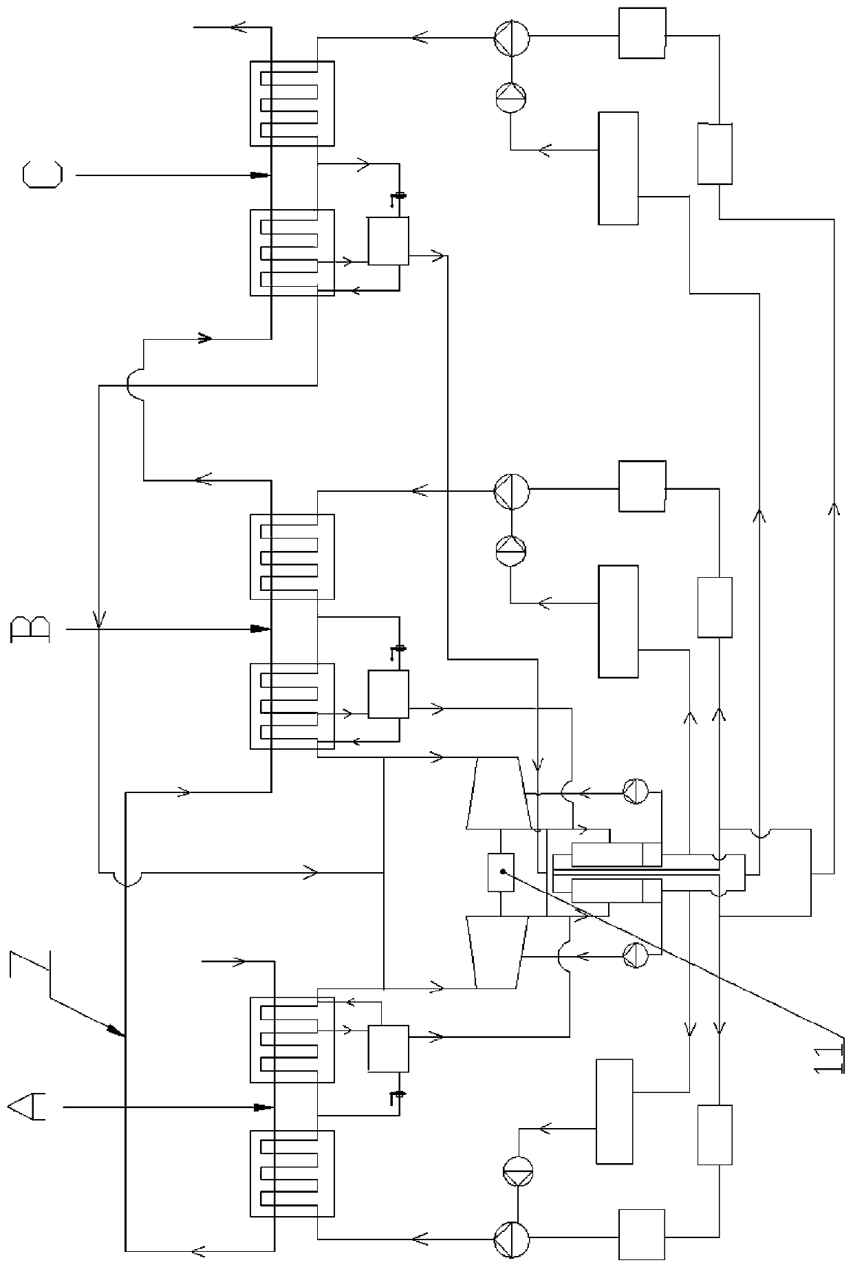
[0021] see figure 1, an embodiment of the compressed gas waste heat recovery power generation system of the present invention, including a compressed gas delivery pipe 7, and also includes a generator 11, a screw expander 10, an evaporator 8, a preheater 5, and a low boiling point organic working fluid storage tank 1 , Working medium pump 2. The compressed gas delivery pipe 7 passes through the provided evaporator 8 and preheater 5 in sequence. The downstream end of the low-boiling point organic working medium storage tank 1 is connected to the organic working medium delivery pipe 4 through the working medium pump 2, and the organic working medium delivery pipe 4 is connected to the steam pipe 18 after passing through the preheater 5 and the evaporator 8 in sequence. The steam pipe 18 is connected to the screw expander 10 , and the screw rotor of the screw expander 10 is connected to the generator 11 . The exhaust port of the screw expander 10 is connected to the inlet of a ...


PUM


Abstract

The invention relates to a power generation system for recycling waste heat of compressed gas. The system comprises a compressed gas conveying pipe, a power generator, a screw expander, an evaporator,a preheater, a low-boiling-point organic working medium storage box and a working medium pump. The compressed gas conveying pipe passes through the evaporator and the preheater which are arranged insequence, the downstream end of the low-boiling-point organic working medium storage box is connected with an organic working medium conveying pipe through the working medium pump, the organic workingmedium conveying pipe is connected with a steam pipe after passing through the preheater and the evaporator in sequence, and the steam pipe is connected with the screw expander. A screw rotor of thescrew expander is connected with the power generator, an exhaust port of the screw expander is connected with an inlet of a separator through a pipe, and a working medium outlet of the separator is connected with a condenser through a pipe. The condenser is connected with the upstream end of the low-boiling-point organic working medium storage box through a pipe, one path of an oil outlet of the separator is connected with a lubricating oil inlet of the screw expander through a main oil pump, and the other path of the oil outlet of the separator is connected with the lubricating oil inlet of the working medium pump through a sub oil pump.

Description

technical field [0001] The invention relates to a power generation system, in particular to a compressed gas waste heat recovery power generation system. Background technique [0002] Compressed gas is widely used as power energy in industrial production, especially in steel and chemical enterprises. In the process of producing compressed gas, a large amount of heat energy will be generated, which will increase the temperature of the compressed gas. Before the compressed gas is sent to the user, in order to ensure the safety of the user's equipment and personal safety, cooling technology must be used to reduce the temperature of the compressed gas to a safe level. temperature. At present, the cooling of compressed gas usually adopts water cooling method, that is, the circulating cooling water pipe passes through the compressed gas cooler, and the cooling circulating water in the circulating cooling water pipe is used to take away the heat of the compressed gas, so that the ...

Claims


Application Information

Patent Timeline
IPC IPC(8): F04B39/06F01K27/02F01K25/10F01C13/00F01C21/04F04B53/18
CPCF04B39/06F01K27/02F01K25/10F01C13/00F01C21/04F04B53/18
Inventor 董荣华
Owner 董荣华
Why Eureka
Try Eureka