Double-channel in-situ infrared reaction tank

An in-situ infrared and reaction cell technology, which is applied in the direction of material analysis, instruments, and measuring devices through optical means, can solve problems such as the inability to take into account the interface species of liquid phase species, and the inability to achieve absolute in-situ analysis, etc.

Active Publication Date: 2020-07-10
ANHUI UNIVERSITY
View PDF4 Cites 2 Cited by
  • Summary
  • Abstract
  • Description
  • Claims
  • Application Information

AI Technical Summary

Problems solved by technology

The existing in-situ ATR test can only select single internal reflection or external reflection mode, which cannot take into account both liquid phase spe

Method used


Image

  • Double-channel in-situ infrared reaction tank
  • Double-channel in-situ infrared reaction tank
  • Double-channel in-situ infrared reaction tank

Examples


Embodiment Construction

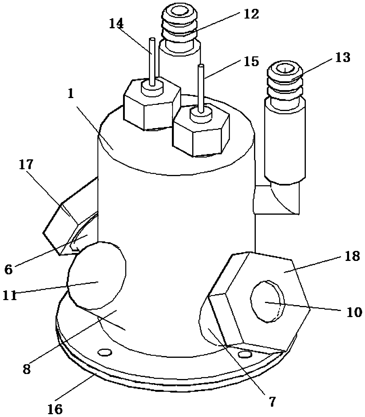
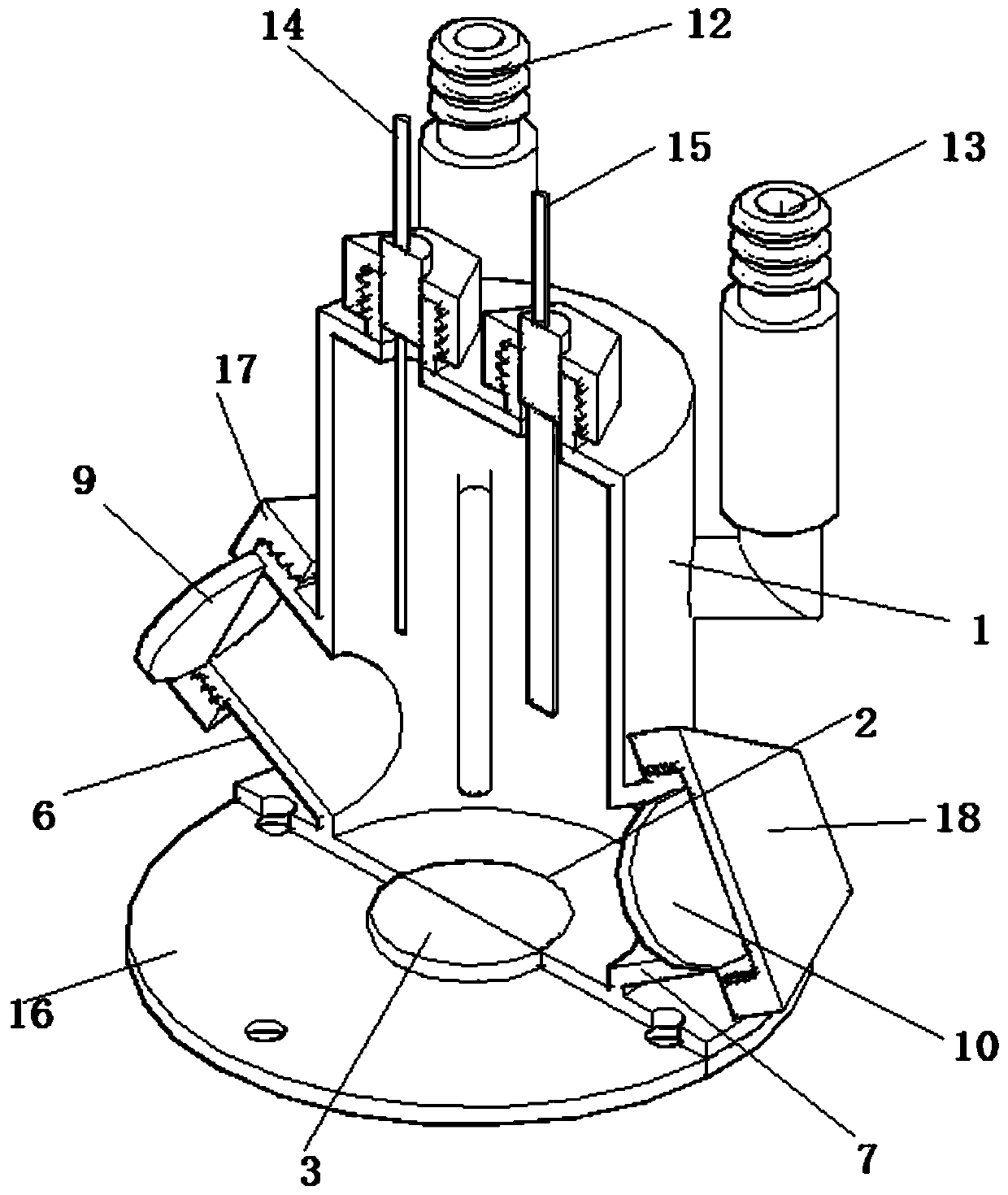
[0020] Reference Figure 1-Figure 4 , The present invention proposes a dual-channel in-situ infrared reaction cell, including a cell body 1; wherein:

[0021] The bottom of the cell body 1 is provided with a sample slot 2, and the sample slot 2 is clamped with a sample stage 3 connected to the external circuit. The top surface of the sample stage 3 is provided with a slot 4 for fixing the attenuated total reflection crystal, and the slot bottom of the slot 4 There is a through hole 5 capable of passing infrared light, the clamping slot 4 is a stepped groove, and the stage diameter of the clamping slot 4 close to the through hole 5 is larger than the stage diameter of the stage away from the through hole 5. A lower gasket 16 that can transmit infrared light is connected to the bottom of the pool body 1.

[0022] The side wall of the pool body 1 is provided with a first window 6, a second window 7, and a third window 8. The first window 6 and the second window 7 are respectively ins...


PUM


Abstract

The invention provides a double-channel in-situ infrared reaction tank, which comprises a tank body, which a sample groove is formed in the bottom end of the tank body, a sample table is clamped in the sample groove, a clamping groove used for fixing a sample is formed in the top surface of the sample table, and a through hole allowing infrared light to penetrate through is formed in the bottom part of the clamping groove; a first window, a second window and a third window are formed in the side wall of the tank body; a first window sheet and a second window sheet which can transmit infrared light are respectively arranged in the first window and the second window; a third window sheet which can transmit sunlight is arranged in the third window; a gas input pipeline and a gas output pipeline which are communicated with the interior of the pool body are arranged on the pool body; and a reference electrode and a counter electrode are arranged at the top end of the pool body. According tothe double-channel in-situ infrared reaction tank, the first window and the second window are arranged to realize the external reflection channel, and the through holes are formed to realize the internal reflection channel, so that internal reflection and external reflection double-channel light paths are formed, and the in-situ infrared spectrum characterization of liquid-phase species and interface species of the photocatalytic reaction is realized.

Description

Technical field [0001] The invention relates to the technical field of environmental protection, in particular to a dual-channel in-situ infrared reaction tank. Background technique [0002] Photocatalytic degradation of gaseous pollutants is an emerging technology to deal with gas pollution, which has attracted widespread attention from environmental protection organizations and scientific research institutions in various countries. Photocatalytic degradation of gas-phase pollutants belongs to a heterogeneous catalytic system (gas-solid phase), which is a complex multi-step process on the surface of a solid catalyst: reactants diffuse from the gas body to the catalyst surface; reactants are adsorbed on the catalyst surface; The catalyst surface undergoes a chemical reaction; the product desorbs from the catalyst surface; the product diffuses from the catalyst surface into the gas phase. Proving the relationship between the steps involved in adsorption, surface reaction, desorpt...

Claims


Application Information

Patent Timeline
IPC IPC(8): G01N21/03G01N21/3577
CPCG01N21/03G01N21/3577
Inventor 孙松魏宇学朱晓娣鲍骏高琛
Owner ANHUI UNIVERSITY
Why Eureka
Try Eureka