Spatial light modulator coupling device without zero-order diffracted light

A technology of spatial light modulator and coupling device, applied in optics, instruments, optical components, etc., can solve the problems of zero-order beam filtering, scattered optical path of the system, etc., to improve accuracy, facilitate adjustment, and avoid the reduction of damage threshold Effect

Active Publication Date: 2020-07-10
XI AN JIAOTONG UNIV
View PDF8 Cites 1 Cited by
  • Summary
  • Abstract
  • Description
  • Claims
  • Application Information

AI Technical Summary

Problems solved by technology

[0003] In order to solve the problems of scattered optical paths and zero-order beam filtering in the background technology, the present invention provides a high-precision light field control, which can suppress zero-order beams without a spatial filter, and a modular and compact spatial light field control device. Coupling device for spatial light modulator without zero-order diffracted light and easy to combine with other systems

Method used


Image

  • Spatial light modulator coupling device without zero-order diffracted light
  • Spatial light modulator coupling device without zero-order diffracted light
  • Spatial light modulator coupling device without zero-order diffracted light

Examples


Embodiment Construction

[0029] Below in conjunction with accompanying drawing and specific embodiment content of the present invention is described in further detail:

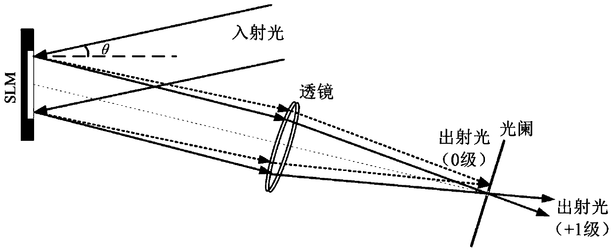
[0030] Such as Figure 4 As shown, the present invention provides a spatial light modulator coupling device without zero-order diffracted light, including a sealed box 3, an asymmetric triangular reflector 2 and a spatial light modulator 1; an asymmetric triangular reflector 2 and a spatial light modulator The device 1 is relatively arranged and placed inside the sealed box 3; the sealed box 3 is provided with a light entrance hole 31 and a light exit hole 32; the incident light passes through the light entrance hole 31, the asymmetric triangular reflector 2, the spatial light modulator 1 and the The symmetrical triangular reflector 2 finally emits from the light exit hole 32 .

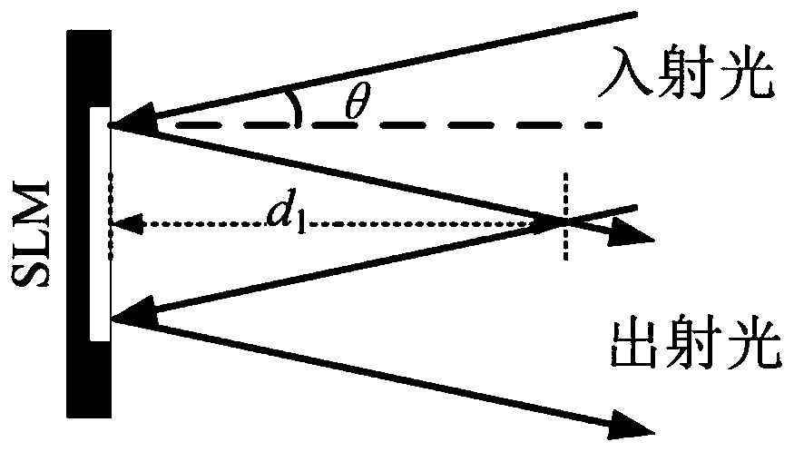
[0031] The positional relationship between the asymmetric triangular reflector 2 and the spatial light modulator 1 satisfies: d2≥d1;

[0032] in:

[0033]...


PUM


Abstract

The invention belongs to the field of spatial light field regulation and control, and relates to a spatial light modulator coupling device without zero-order diffracted light. The device comprises a sealing box, an asymmetric triangular reflector and a spatial light modulator. The asymmetric triangular reflector and the spatial light modulator are oppositely arranged and are arranged in the sealing box; a light inlet hole and a light outlet hole are formed in the sealing box; incident light sequentially passes through the light inlet hole, the asymmetric triangular reflector, the spatial lightmodulator and the asymmetric triangular reflector and then is emitted out from the light outlet hole. The zero-order diffracted light-free spatial light modulator coupling device has the advantages of high-precision light field regulation and control, zero-order light beam suppression without a spatial filter, modularization and compactness of the spatial light field regulation and control deviceand easiness in combination with other systems.

Description

technical field [0001] The invention belongs to the field of spatial light field control, and relates to a spatial light modulator coupling device, in particular to a spatial light modulator coupling device without zero-order diffracted light. Background technique [0002] The invention of the laser in 1960 greatly promoted the development of natural science research, such as laser life science, optical information processing, optical micro-nano processing and many other laser-based scientific research fields emerged. The main limitation of ordinary commercial lasers is that the output mode is fixed, usually the fundamental mode Gaussian beam, which cannot meet the requirements of modern scientific research and applications for the specific distribution of the amplitude, phase and polarization state of the light field. The spatial light field control technology based on the spatial light modulator to control the spatial parameters of the light field converts the fundamental ...

Claims


Application Information

Patent Timeline
Patent Type & Authority Applications(China)
IPC IPC(8): G02B17/06G02B27/42
CPCG02B17/0668G02B27/4233
Inventor 梁言生雷铭汪召军
Owner XI AN JIAOTONG UNIV
Why Eureka
Try Eureka