Pole plate group continuous slot entering device for lead-acid storage battery

A lead-acid battery and battery technology, which is applied in the construction, transportation and packaging of lead-acid batteries and lead-acid batteries, can solve the problems of inability to continuously enter the tank and low work efficiency, and achieve good tank entry effect and tank entry. Accurate method and the effect of reducing production costs

Inactive Publication Date: 2020-07-10
长兴水木机电有限公司
View PDF0 Cites 2 Cited by
  • Summary
  • Abstract
  • Description
  • Claims
  • Application Information

AI Technical Summary

Problems solved by technology

[0005] The purpose of the present invention is to address the deficiencies of the prior art, by arranging the pole group clamping mechanism to cooperate with the shell clamping mechanism, to realize the cooperation and clamping of the pole group and the battery case during the transmission process, and then to realize continuous slotting work, and the way of entering the slot

Method used


Image

  • Pole plate group continuous slot entering device for lead-acid storage battery
  • Pole plate group continuous slot entering device for lead-acid storage battery
  • Pole plate group continuous slot entering device for lead-acid storage battery

Examples


Embodiment 1

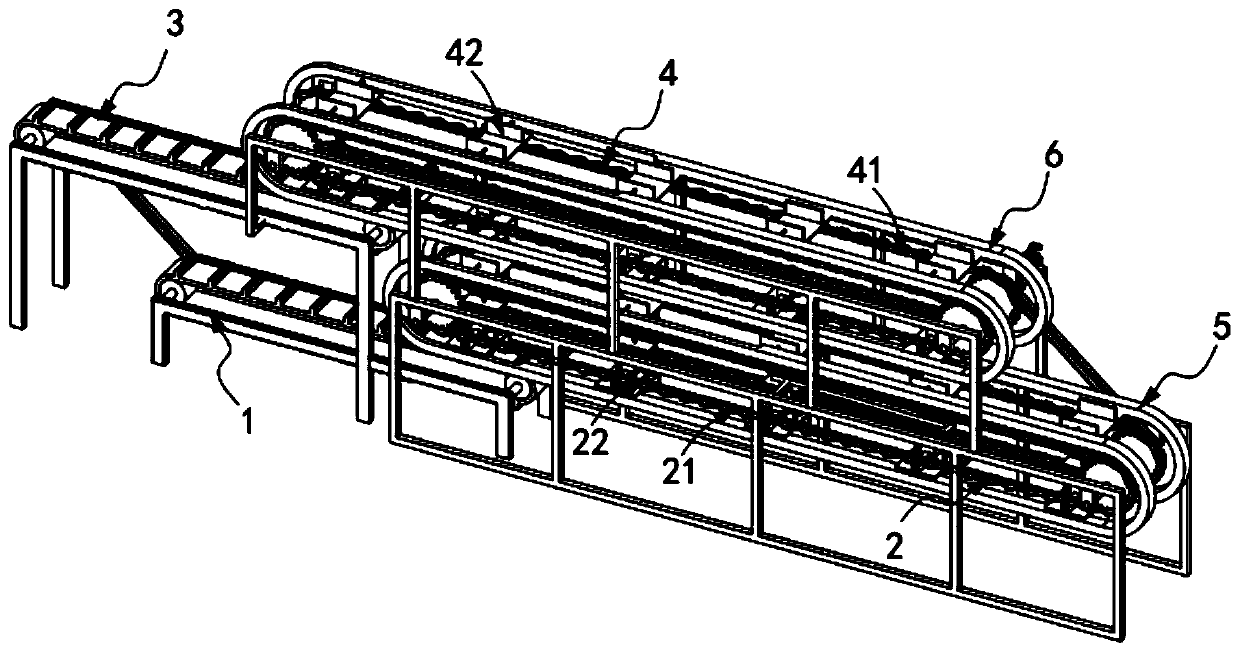
[0048] Such as figure 1 As shown, a lead-acid storage battery uses an electrode group continuous slotting device, including:

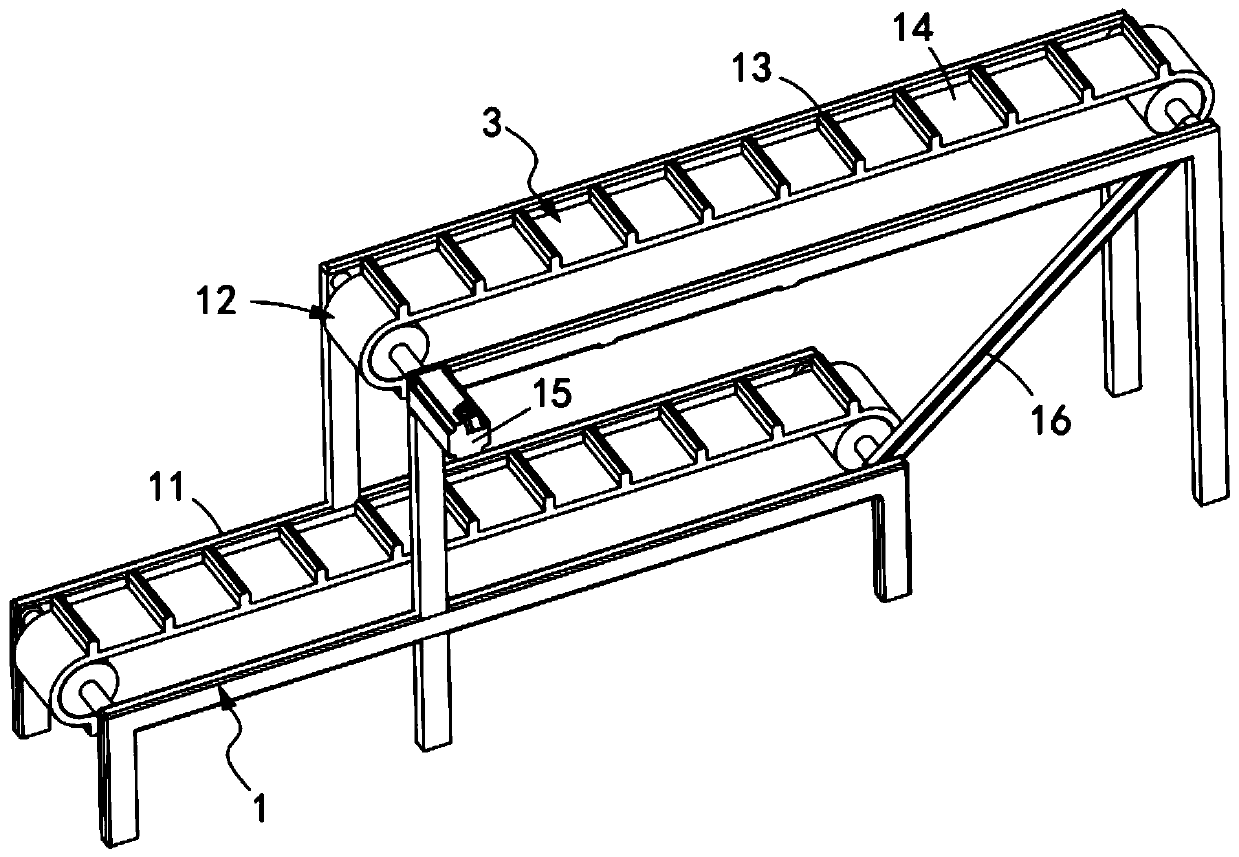
[0049] The pole group transmission mechanism 1, the pole group transmission mechanism 1 is used to sequentially transport several groups of pole groups 10 backward;

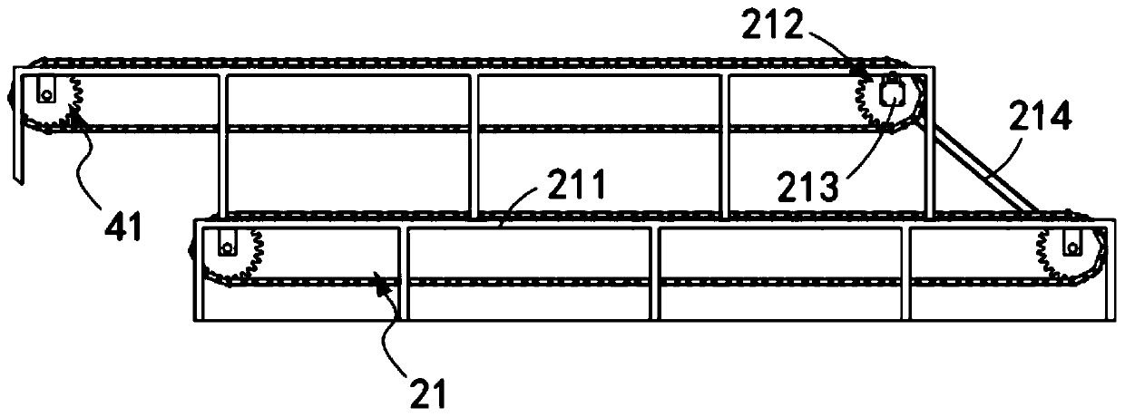
[0050] The pole group clamping mechanism 2, the pole group clamping mechanism 2 is located above the pole group transmission mechanism 1, and it includes a first transmission assembly 21 and a number of equidistant along the transmission direction of the first transmission assembly 21. A first tightening component 22 assembled and installed on the first conveying component 21;

[0051] A shell transmission mechanism 3, which is arranged above the pole group clamping mechanism 2, and is used to sequentially transport several groups of battery shells backwards; and

[0052] The shell clamping mechanism 4, the shell clamping mechanism 4 is located above the shell transmission mechanism 3, ...

Embodiment 2

[0074] As shown in Figure 16, Figure 14 As shown in FIG. 15 , the parts that are the same as or corresponding to those in the first embodiment are marked with the corresponding reference numerals of the first embodiment. For the sake of brevity, only the differences from the first embodiment are described below. The difference between this embodiment two and embodiment one is:

[0075] Further, as shown in Figure 16, Figure 14 As shown in FIG. 15, the third guide assembly 7 includes a sliding seat 71 vertically slidably arranged on the base 221 of the first tightening assembly 22, a connecting shaft 72 fixedly connected with the sliding seat 71, and The connecting shaft 72 is fixedly connected to the mounting plate 73, the control rod 74 installed on the mounting plate 73, and the guide track c75. The mounting plate 73 is fixedly connected to the outer wall of the base 221 through two sets of telescopic units b76. The telescopic unit b76 includes a telescopic rod b77 and a...


PUM


Abstract

The invention relates to a pole plate group continuous slot entering device for a lead-acid storage battery. The device comprises a pole plate group conveying mechanism; a pole group clamping mechanism which comprises a first conveying assembly and a first hooping assembly; a housing transmission mechanism; and a housing clamping mechanism which comprises a second conveying assembly and a second hooping assembly. A first guide assembly mounted on a rack controls the first hooping assembly to clamp the pole plate group in a conveying state and convey the pole plate group backwards; a second guide assembly installed on the rack controls the second hooping assembly to clamp the pole plate group in the conveying state and convey the pole plate group backwards; and a third guide assembly mounted on the rack lifts the first hooping assembly and inserts the first hooping assembly into the storage battery housing clamped by the correspondingly arranged second hooping assembly. According to theinvention, the technical problem of low working efficiency caused by incapability of realizing continuous slot entering work due to waiting of the next group of pole groups to be subjected to slot entering work when the previous group of pole groups are subjected to slot entering work through slot entering work of the pressing plate is solved.

Description

technical field [0001] The invention relates to the technical field of lead-acid batteries, in particular to an electrode group continuous slotting device for lead-acid batteries. Background technique [0002] In the production of the front battery, when the pole group and the battery case are fitted into the slot, they are manually inserted into the slot. However, manual slotting cannot ensure that each pole group enters the slot with the same force. The difference and the inconsistency of the internal liquid volume of the battery have a serious impact on the consistency of the product capacity; and in the production process, the manual insertion of the battery into the tank requires a lot of physical strength, and the continuous operation of the staff is labor-intensive. For the current lack of labor, mass production pose very serious challenges. [0003] The patent document with the patent number CN13100937749 discloses a battery pole group slotting device, which relates...

Claims


Application Information

Patent Timeline
IPC IPC(8): H01M10/14B65G17/12B65G17/34B65G17/46
CPCB65G17/123B65G17/34B65G17/46H01M10/14Y02E60/10Y02P70/50
Inventor 周杰庄阳
Owner 长兴水木机电有限公司
Why Eureka
Try Eureka