Flexible loop closing device and control method thereof

A flexible, voltage source-type technology, applied in the direction of circuit devices, AC network circuits, electrical components, etc., can solve the problems of not improving performance, limiting power flow and optimizing operation functions, etc., to achieve the effect of ensuring efficient operation, fast power supply, and flexible switching

Active Publication Date: 2020-07-10
STATE GRID JIANGSU ELECTRIC POWER CO ELECTRIC POWER RES INST +2
View PDF3 Cites 4 Cited by
  • Summary
  • Abstract
  • Description
  • Claims
  • Application Information

AI Technical Summary

Problems solved by technology

This technology improves the disadvantages of large capacity and low cost of the traditional flexible ring closing device, but has the following disadvantages: (1) The announced device, control system and method do not improve the defect of low efficiency of the flexible ring closing device under non-faulty operation; ( 2) The announced device only has power flow optimization dispatching and fault recovery functions under normal operation conditions, and the defect of low efficiency under normal operation conditions limits its power flow optimization operation function

Method used


Image

  • Flexible loop closing device and control method thereof
  • Flexible loop closing device and control method thereof
  • Flexible loop closing device and control method thereof

Examples


Embodiment 1

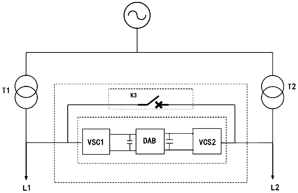
[0045] An embodiment of the present invention provides a flexible ring closing device, such as figure 1 shown, including:

[0046] The back-to-back high-frequency isolation unit includes a first voltage source converter VSC1, a dual active bridge conversion circuit DAB, and a second voltage source converter VSC2 connected in series;

[0047] A switch K3 is connected in parallel with the back-to-back high-frequency isolation unit, one end is connected to the first voltage source converter VSC1 , and the other end is connected to the second voltage source converter VSC2 .

[0048] In practical applications, the switch K3 is generally a mechanical switch.

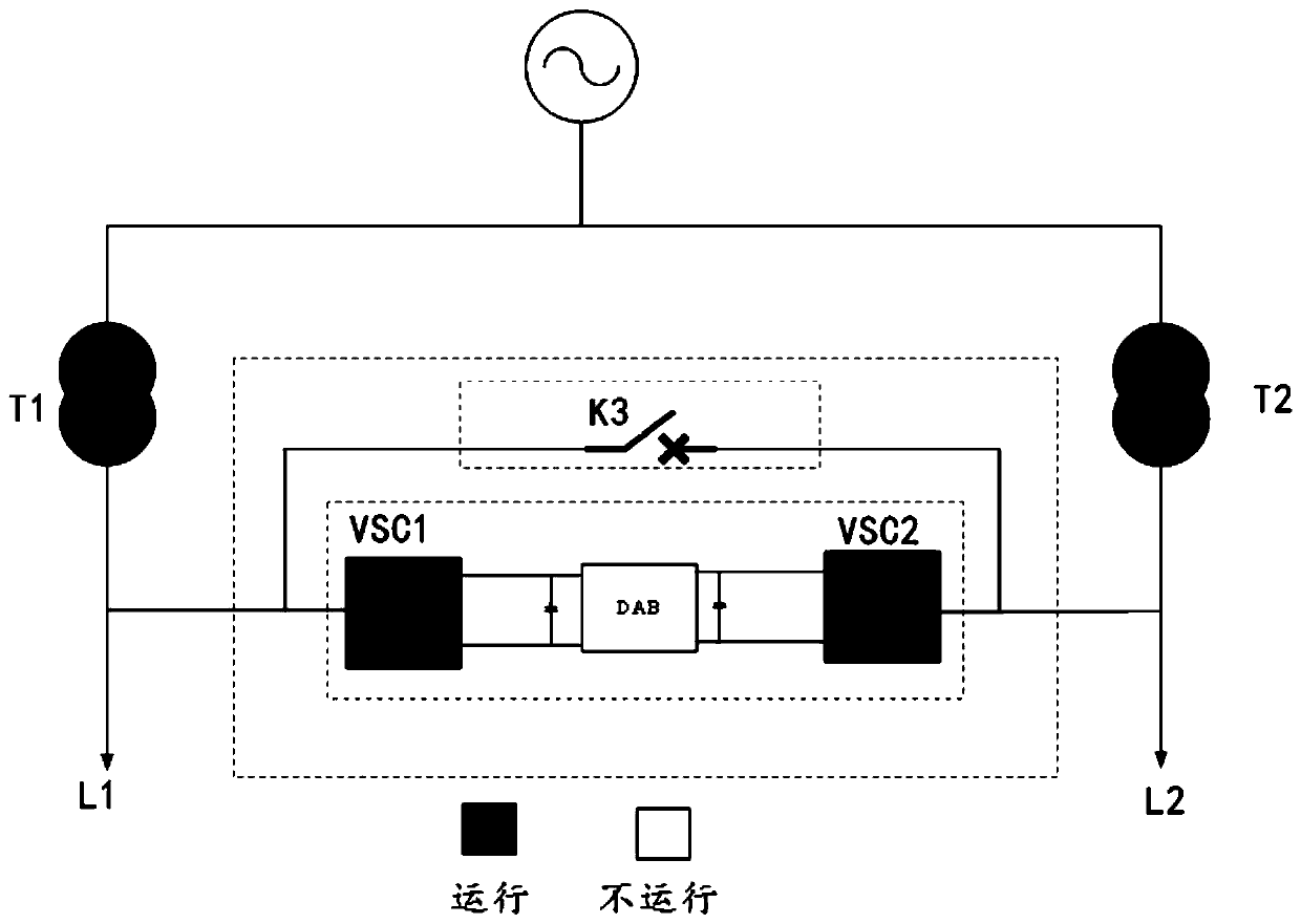
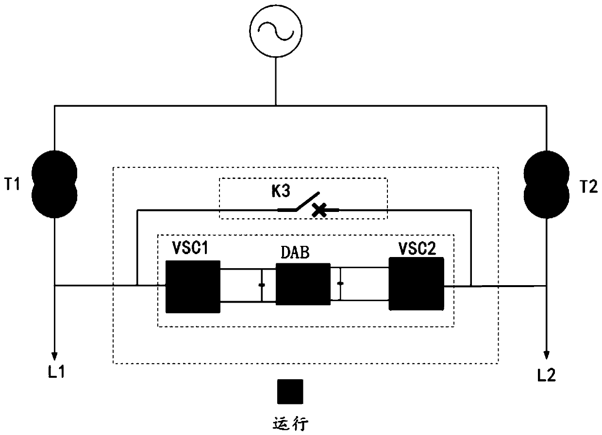
[0049] In a specific implementation manner of the embodiment of the present invention, when monitoring the distribution network connected to the flexible loop closing device, when the voltage deviation is caused by the output change of the distributed power supply, the flexible loop closing device switches to reactive power ...

Embodiment 2

[0059] An embodiment of the present invention provides a control method based on the flexible ring closing device described in any one of Embodiment 1, comprising the following steps:

[0060] monitoring the operating status of the distribution network connected to the flexible loop closing device;

[0061] Based on the operating state of the distribution network, switch the flexible loop closing device to a corresponding working mode.

[0062] In a specific implementation manner of the embodiment of the present invention, the switching of the flexible loop closing device to a corresponding working mode based on the operating state of the distribution network includes:

[0063] When the distribution network connected to the flexible loop closing device has a voltage deviation caused by a change in the output of the distributed power supply, the flexible loop closing device switches to the reactive power compensation mode; the dual active bridge conversion circuit DBA is switch...


PUM


Abstract

The invention discloses a flexible loop closing device and a control method thereof. The device comprises a back-to-back high-frequency isolation unit and a switch. The back-to-back high-frequency isolation unit comprises a first voltage source type converter, a dual-active-bridge conversion circuit and a second voltage source type converter which are sequentially connected in series. The switch is connected with the back-to-back high-frequency isolation unit in parallel, one end of the switch is connected with the first voltage source type converter, and the other end of the switch is connected with the second voltage source type converter. According to the invention, flexible interconnection between different alternating current areas and rapid power supply of a fault area can be realized, flexible switching of transformer operation modes can be realized, and efficient operation of the system is ensured.

Description

technical field [0001] The invention belongs to the technical field of distribution network optimization operation control, and specifically relates to a flexible loop closing device and a control method thereof, in particular to a high-frequency isolation type flexible loop closing device and a control method thereof. Background technique [0002] my country's distribution network adopts the design principle of "closed-loop design, open-loop operation". By adjusting the state of contact switches and segment switches, the network structure can be optimized, the efficient operation of the distribution network can be maintained, and the power supply recovery in faulty areas can be realized. However, at the instant of switching operation based on the mechanical switch, the system contains a large inrush current, which affects the stable operation of the system. The flexible loop closing device proposed by the researchers can realize the flexible interconnection of AC regions wi...

Claims


Application Information

Patent Timeline
Patent Type & Authority Applications(China)
IPC IPC(8): H02J3/00
CPCH02J3/00Y02E40/30
Inventor 葛雪峰袁宇波史明明周琦袁晓冬杨景刚陈舒陈久林
Owner STATE GRID JIANGSU ELECTRIC POWER CO ELECTRIC POWER RES INST
Why Eureka
Try Eureka