Child head fixator
A head immobilizer and children's technology, which is applied in the direction of stereotaxic surgical instruments, eye masks, earmuffs, etc., can solve problems such as easy struggle, twisting, getting stuck in children, and difficult fixation, so as to reduce fatigue and prevent Effect of head movement, workload reduction
- Summary
- Abstract
- Description
- Claims
- Application Information
AI Technical Summary
Problems solved by technology
Method used
Image
Examples
Embodiment 1
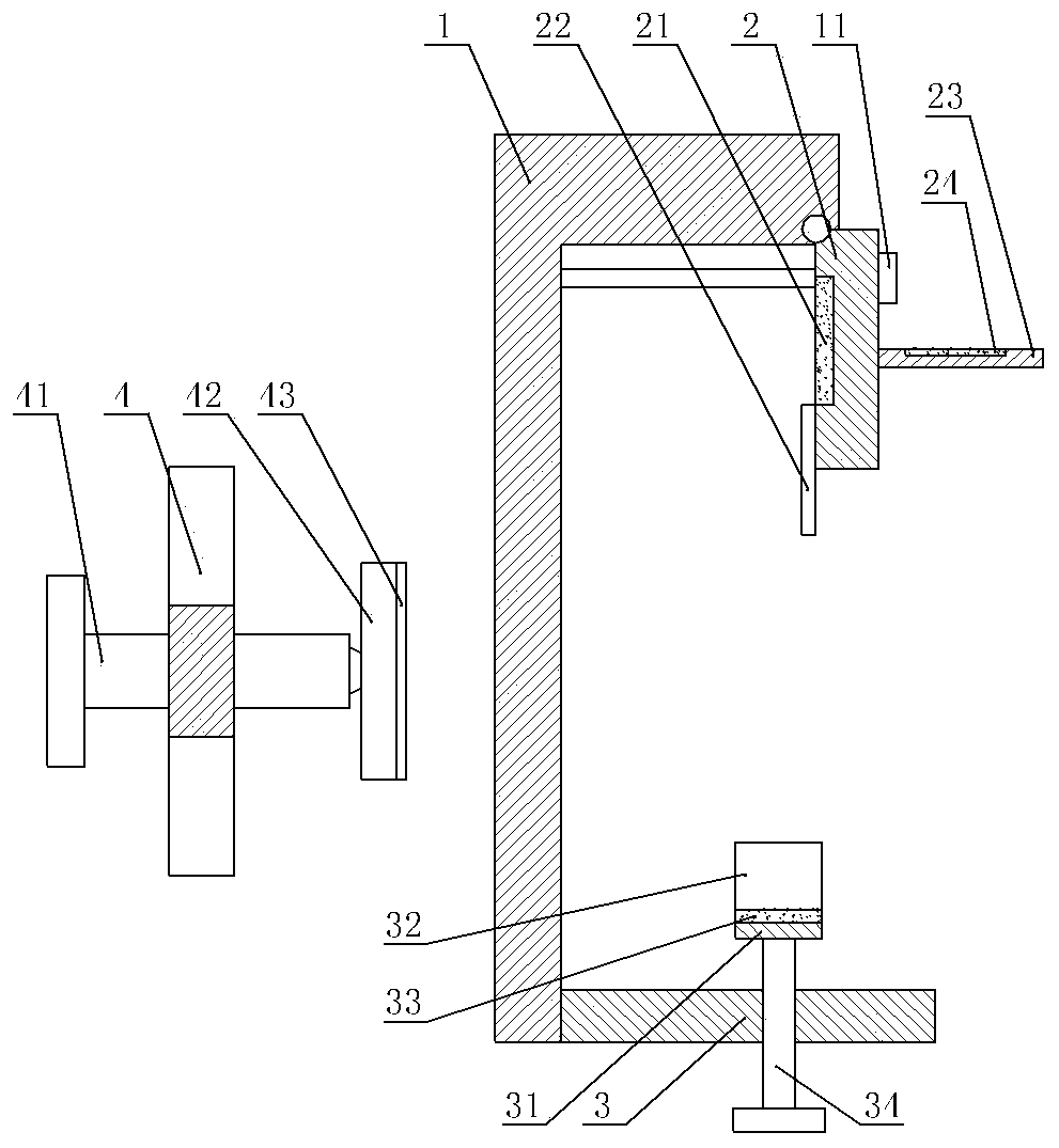
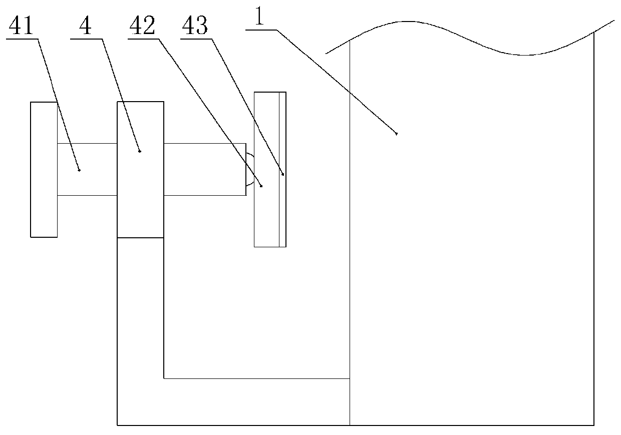
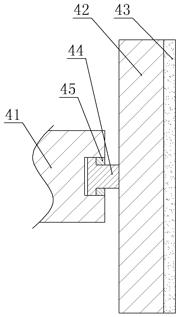
[0037] Children's head immobilizers, such as figure 1 As shown, it includes an installation unit and a fixing unit, the installation unit includes a base 1 and a pressing piece, and the pressing piece includes a pressing bar 41 and a pressing block 4, as figure 2 As shown, the compression block 4 is L-shaped, and the compression block 4 is welded on the left end of the base 1, the compression rod 41 is perpendicular to the base 1 and runs through the compression block 4, and the compression rod 41 is threaded with the compression block 4. Press bar 41 right-hand ends are connected with briquetting block 42, and briquetting block 42 left end is ball-hinged with pressing bar 41 right-hand ends, and briquetting block 42 right wall is glued with non-slip pad 43, and anti-slip pad 43 among the present embodiment adopts elastic rubber material. In specific implementation, such as image 3 As shown, a T-shaped connecting shaft 44 can also be welded at the left end of the pressing b...
Embodiment 2
[0048] The difference from Example 1 is that, as Figure 5 As shown, the base 1 in this embodiment includes a base 12 and an adjusting seat 13 , the adjusting base 13 in this embodiment is hinged to the right wall of the base 12 , and the pressing block 4 is welded on the base 12 . The upper limit member 2, the upper fixing member 11, the lower limit assembly and the lower fixing member are all installed on the adjustment seat 13, and the connection method is the same as the connection method with the base 1 in the first embodiment.
[0049] The right end of the base body 12 is integrally formed with two bumps 14, the left wall of the adjustment seat 13 is welded with a screw 15 transversely, the screw 15 runs through the two bumps 14 and there is a gap for the screw 15 to rotate . Such as Figure 6 As shown, the two bumps 14 are respectively located on the left and right sides of the adjustment seat 13, and the left and right ends of the screw 15 are provided with T-shaped ...
PUM
 Abstract
Description
Claims
Application Information
 - R&D
- Intellectual Property
- Life Sciences
- Materials
- Tech Scout
- Unparalleled Data Quality
- Higher Quality Content
- 60% Fewer Hallucinations
Browse by: Latest US Patents, China's latest patents, Technical Efficacy Thesaurus, Application Domain, Technology Topic, Popular Technical Reports.
© 2025 PatSnap. All rights reserved.Legal|Privacy policy|Modern Slavery Act Transparency Statement|Sitemap|About US| Contact US: help@patsnap.com


