Flue gas mixing structure for desulfurization and denitrification

A flue gas mixing, desulfurization and denitrification technology, applied in the field of desulfurization and denitrification, can solve the problems of flue gas discharge and poor flue gas treatment effect, achieve uniform mixing and improve treatment effect

Inactive Publication Date: 2020-07-14
黄延兵
View PDF0 Cites 0 Cited by
  • Summary
  • Abstract
  • Description
  • Claims
  • Application Information

AI Technical Summary

Problems solved by technology

[0003] In the prior art, the liquid used to treat flue gas is often sprayed down from the top to contact with the flue gas, and the flue gas mostly enters in concentratedly. Due

Method used


Image

  • Flue gas mixing structure for desulfurization and denitrification
  • Flue gas mixing structure for desulfurization and denitrification
  • Flue gas mixing structure for desulfurization and denitrification

Examples


Embodiment 1

[0037] The currently widely used desulfurization and denitrification integrated technology is mainly the combination of wet flue gas desulfurization and selective catalytic reduction or selective non-catalytic reduction technology denitrification. Wet flue gas desulfurization is commonly used calcium method using lime or limestone, and the desulfurization efficiency can reach 90%. This technology is mature and reliable, but the flue gas needs to be preheated.

[0038] In the prior art, the liquid used to treat flue gas is often sprayed down from the top to contact with the flue gas, and the flue gas mostly enters in concentratedly. Due to the strong fluidity of the gas, the treated liquid is not fully mixed with the flue gas, resulting in smoke. The gas is exhausted, and the effect of flue gas treatment is poor.

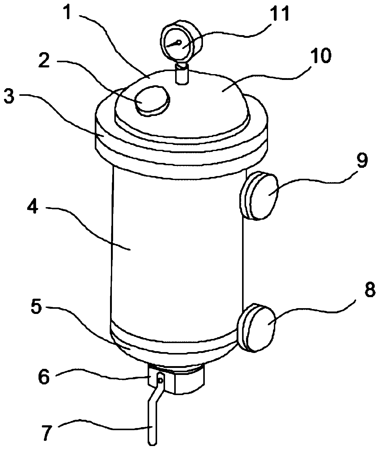
[0039] Therefore, aiming at the above problems, the present invention provides a flue gas mixing structure for desulfurization and denitrification.

[0040] Specifi...

Embodiment 2

[0052] The embodiment of the present invention is further limited on the basis of embodiment 1.

[0053] In order to further improve the mixed treatment effect of flue gas.

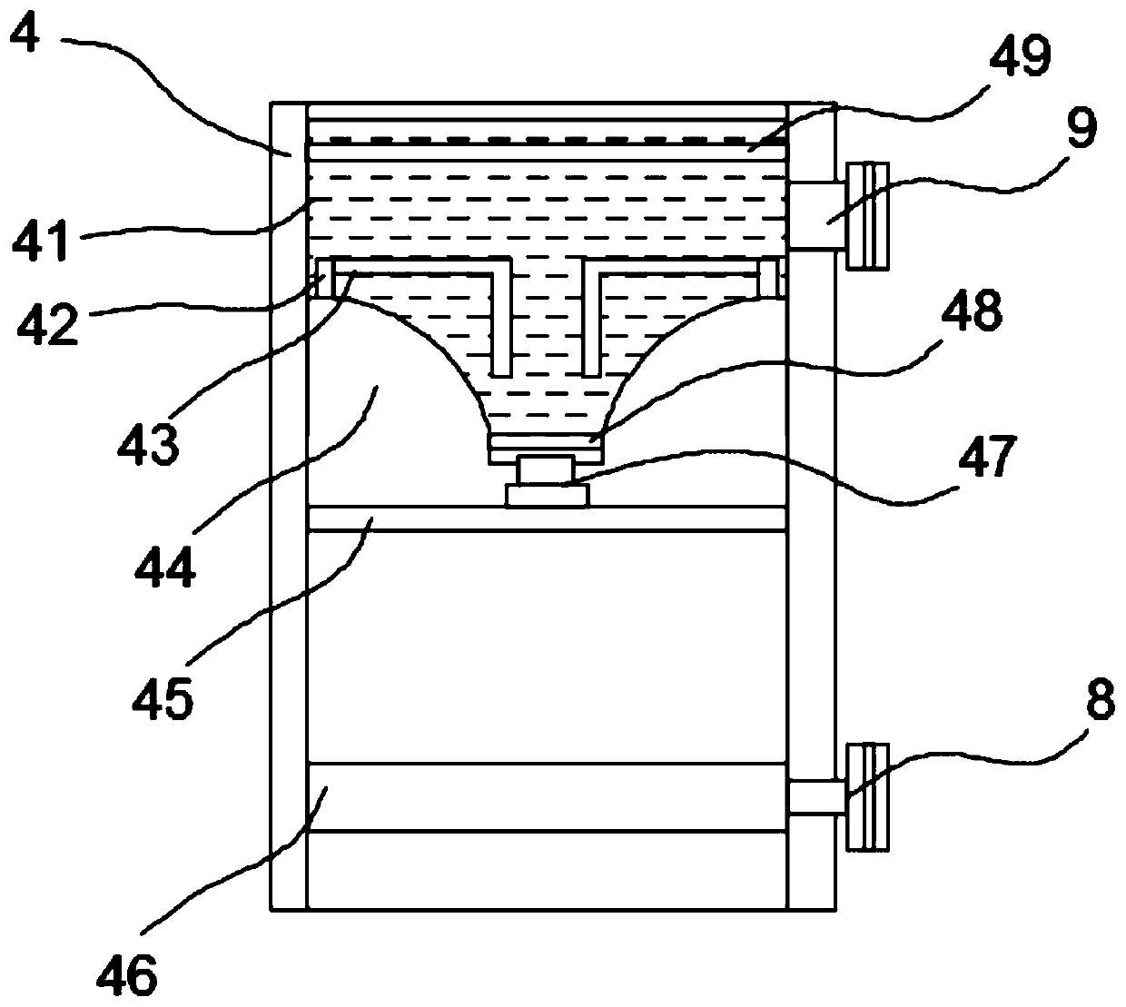
[0054] see figure 2 with image 3 , at the bottom of the liquid tank 41 near the side of the spray plate 45, there are a plurality of gas collecting chambers 44 distributed in an annular array, and the gas collecting chambers 44 are connected to the inside of the liquid tank 41 through the gas collecting pipe 42, and in the liquid tank 41 An air diffuser 43 is arranged inside.

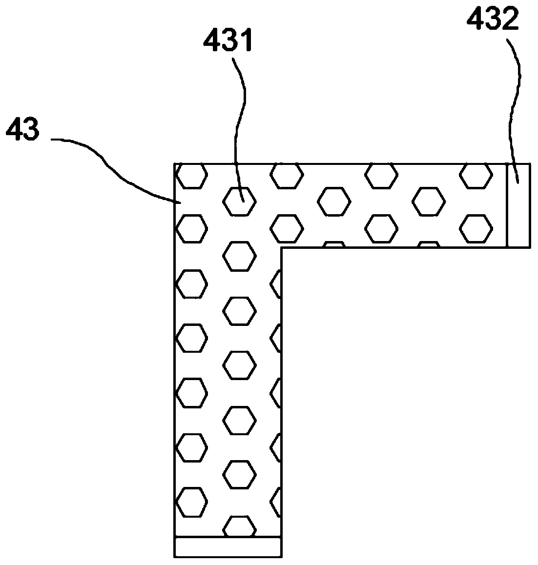
[0055] The air diffuser pipe 43 is L-shaped, and a mounting ring 432 is installed at both ends of the air diffuser pipe 43 , and a plurality of one-way air outlet holes 431 are opened in the air diffuser pipe 43 .

[0056] A defoaming net 49 is installed inside the liquid tank 41 at the upper end of the diffuser pipe 43 .

[0057]Furthermore, the flue gas that has not been completely treated by the spraying plate 45 enters th...


PUM


Abstract

The invention particularly relates to a flue gas mixing structure for desulfurization and denitrification, which belongs to the field of desulfurization and denitrification, and comprises a tank bodyand a gas guide disc, wherein the gas guide disc is arranged in the tank body, and a spraying disc is mounted in the tank body at the upper end of the gas guide disc and is connected to the liquid tank through a suction pump; an outer fixing ring II used for fixing is arranged on the air guide disc, a disc type air guide pipe is installed in the outer fixing ring II, and a plurality of air outletholes are formed in the side wall of the disc type air guide pipe; an outer fixing ring I is arranged on the spraying disc; a plurality of liquid guide pipes which are distributed in an array manner are mounted in the outer fixing ring I; a liquid outlet hole is formed in the lower end of the liquid guide pipe; liquid for treating flue gas can be uniformly sprayed through a plurality of liquid outlet holes in the liquid guide pipes distributed in an array mode, the flue gas enters the disc type gas guide pipe through the gas inlet pipe in a combined mode, the multiple gas outlet holes distributed in the array mode are used for uniformly discharging gas in a multi-range mode, uniform mixing is achieved, and the flue gas treatment effect is improved.

Description

technical field [0001] The invention relates to the field of desulfurization and denitrification, specifically a flue gas mixing structure for desulfurization and denitrification. Background technique [0002] The currently widely used desulfurization and denitrification integrated technology is mainly the combination of wet flue gas desulfurization and selective catalytic reduction or selective non-catalytic reduction technology denitrification. Wet flue gas desulfurization is commonly used calcium method using lime or limestone, and the desulfurization efficiency can reach 90%. This technology is mature and reliable, but the flue gas needs to be preheated. [0003] In the prior art, the liquid used to treat flue gas is often sprayed down from the top to contact with the flue gas, and the flue gas mostly enters in concentratedly. Due to the strong fluidity of the gas, the treated liquid is not fully mixed with the flue gas, resulting in smoke. The gas is exhausted, and the...

Claims


Application Information

Patent Timeline
IPC IPC(8): B01F3/04B01D53/86B01D53/56B01D53/50
CPCB01D53/504B01D53/8631B01D2258/0283B01D2251/404B01F23/2321B01F23/23
Inventor 黄延兵
Owner 黄延兵
Why Eureka
Try Eureka