

Tool equipment for stripping sleeve rod and sleeve based on machining
A technology of mechanical processing and tooling equipment, applied in metal processing equipment, metal processing, manufacturing tools, etc., can solve the problems of difficult clamping and fixing, poor universality, and pinching sleeve rods.
- Summary
- Abstract
- Description
- Claims
- Application Information
AI Technical Summary
Problems solved by technology
Method used
Image

Examples
Embodiment
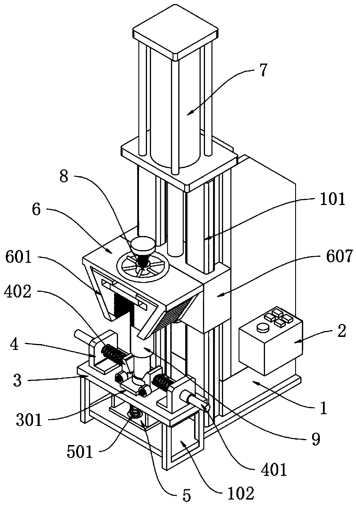
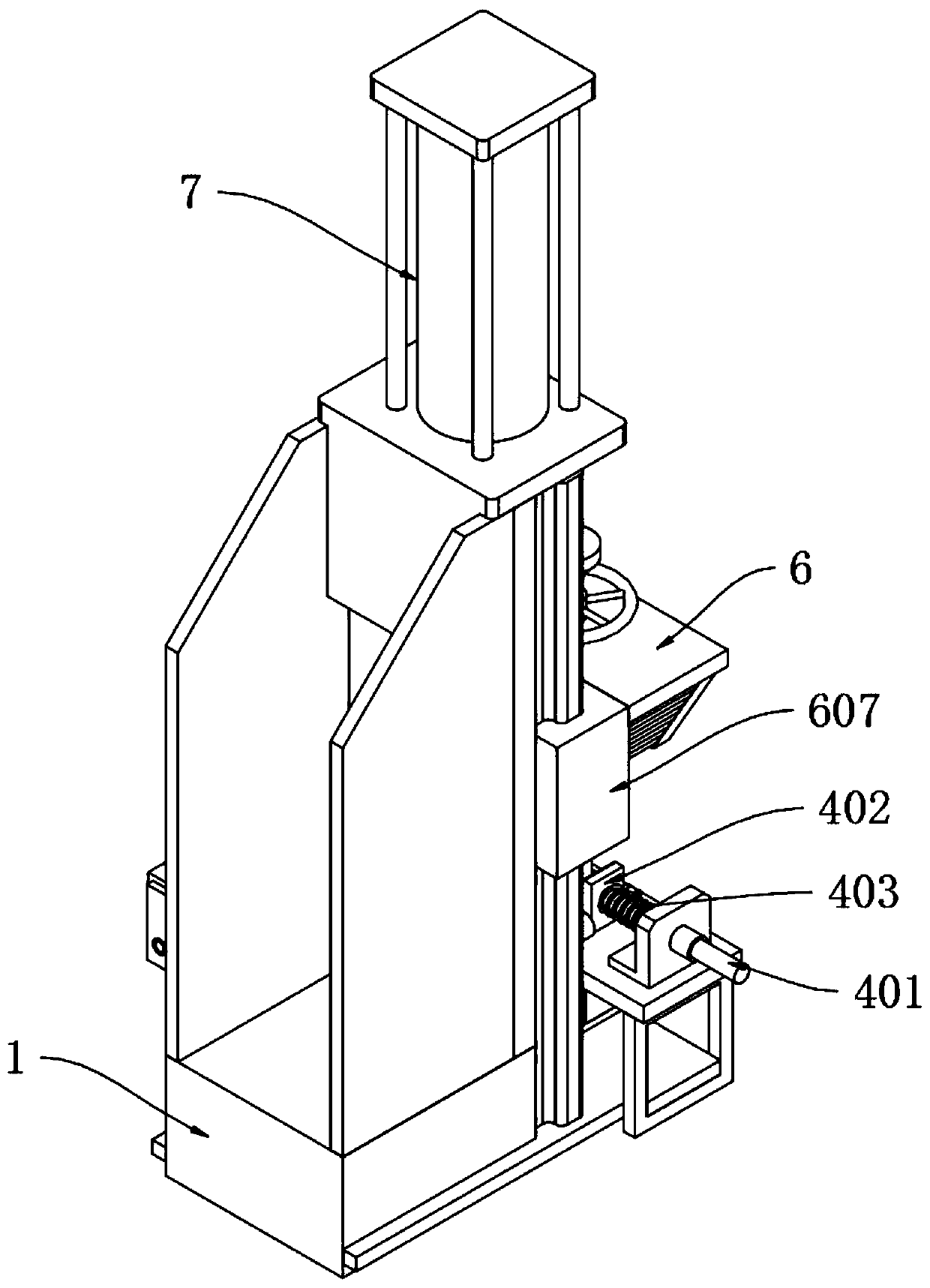
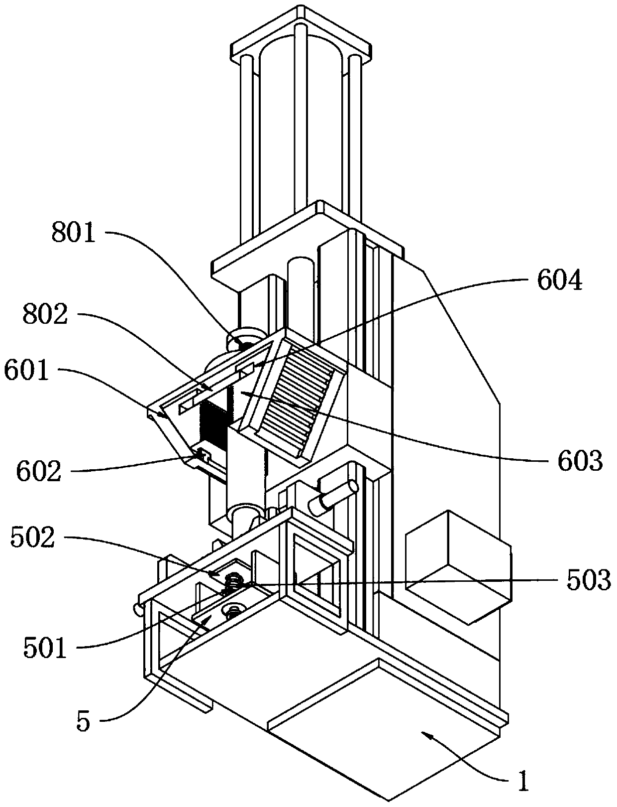
[0035] as attached figure 1 To attach Figure 8 Shown:
[0036] The present invention provides a tooling device based on the stripping of sleeve rods and sleeves for mechanical processing, including a tooling body 1; an adapter box 2 is fixedly installed on the right side wall of the tooling body 1; the lower end of the tooling body 1 is fixed vertically forward Stripping platform 3 is installed; The top plane of stripping platform 3 is symmetrically fixedly installed with horizontal clamping mechanism 4; In the stripping platform 3 between two clamping mechanisms 4, stripping seat 5 is vertically installed, and its stripping seat 5 is fixed. Installed on the bottom plane of the peeling table 3; the upper end of the peeling seat 5 is vertically inserted with a sleeve rod sleeve assembly 9;
[0037] The peeling table 3 includes an adaptive hole 301, and the middle part of the peeling table 3 is provided with a rectangular adaptive hole 301 that penetrates up and down, and the...
PUM
 Abstract
Description
Claims
Application Information