Water purifier system with flush valve

A flushing valve and pure water machine technology, applied in water/sewage treatment, water/sewage multi-stage treatment, water/sludge/sewage treatment, etc., can solve problems such as high failure rate, high cost, and complex structure

Pending Publication Date: 2020-07-14
宁波川渡流体科技有限公司
View PDF0 Cites 0 Cited by
  • Summary
  • Abstract
  • Description
  • Claims
  • Application Information

AI Technical Summary

Problems solved by technology

[0003] At present, in the pure water machine system, a flushing solenoid valve is generally installed on the concentrated water drain pipe to control the flushing of the reverse osmosis membrane unit. After the pure water machine system stops water production, the flushing solenoid valve is opened to allow a large flow of concentrated water to flow out. Then flush the reverse osmosis membrane unit, but the flushing solenoid valve with this configuration has a complex structure, high cost, large volume, and high failure rate in the later stage, so more lines need to be arranged to control the flushing solenoid valve

Method used


Image

  • Water purifier system with flush valve
  • Water purifier system with flush valve
  • Water purifier system with flush valve

Examples


Embodiment 1

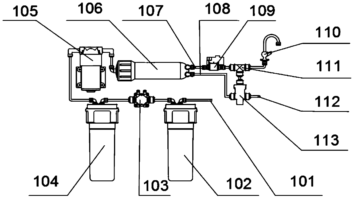
[0031] Such as figure 1 As shown, the present invention connects the concentrated water inlet 1 of the flushing valve 113 on the concentrated water pipe 108 of the large flux reverse osmosis filter group 106, the drain port 11 of the flushing valve 113 is connected to the concentrated water discharge pipe 112, and the flushing valve 113 The upper end communicates with the vertical opening of the tee 111 on the clean water pipe 107, the tee 111 is located between the high pressure switch 109 and the clean water faucet 110, and the two horizontal openings are respectively the high pressure switch 109 and the clean water faucet 110 When the pure water mechanism is used, the flushing valve 113 is in a conduction state with a small flow rate, the high-pressure switch 109, the water shut-off valve 103 and the booster pump 105 are activated, and the raw water enters from the raw water pipe 101 and passes through the first filter group 102, the second The second filter group 104 pre-f...

Embodiment 2

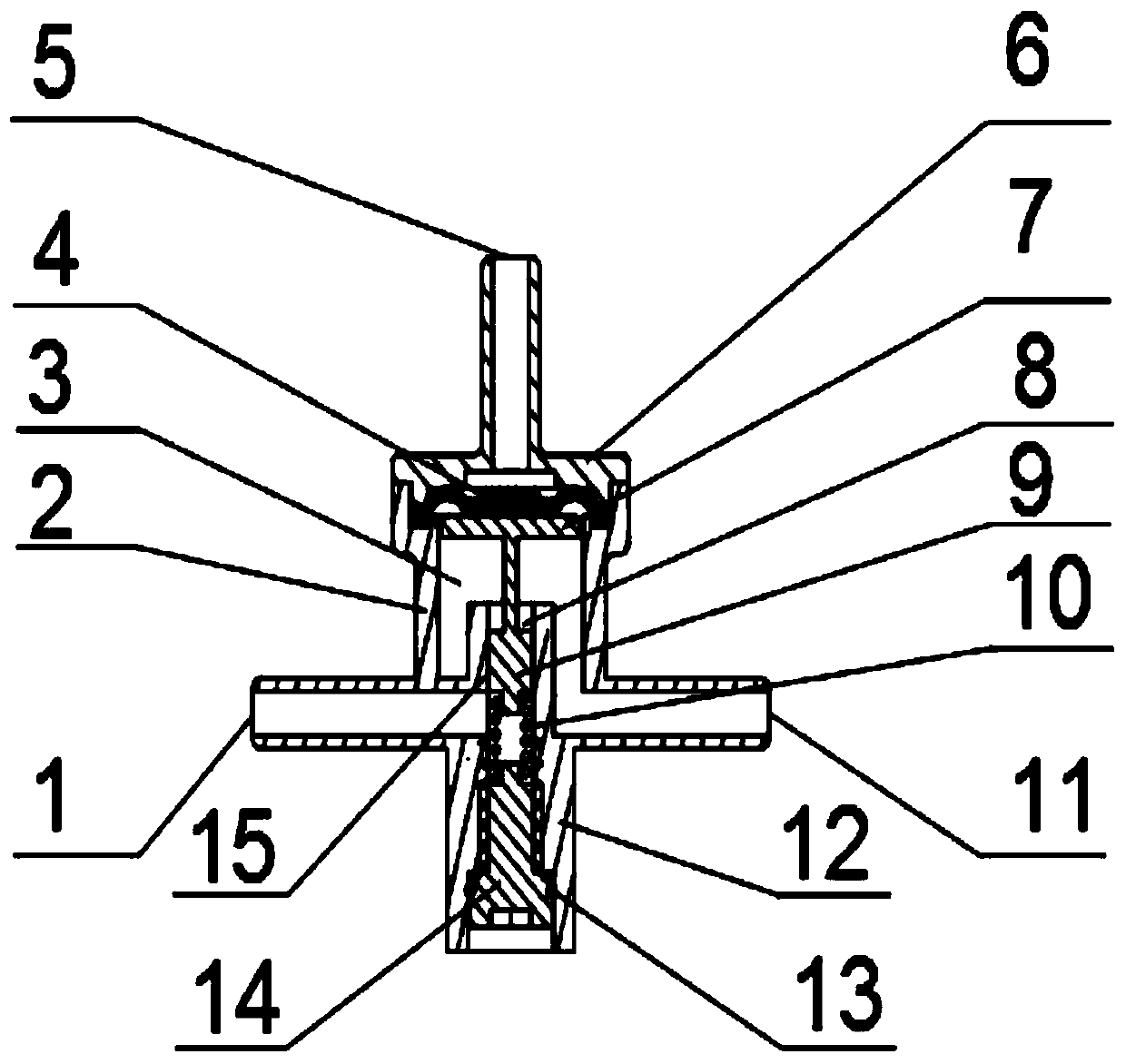
[0033] In this example, if figure 2 As shown, the flushing valve 113 also includes a valve body 2, the upper end of the valve body 2 is provided with a matching bonnet 6, and the clean water inlet 5 on the bonnet 6 communicates with the clean water pipe 107. During the pure water machine water process, the clean water Continuously flow out from the water purification faucet 110. At this time, the water pressure in the water purification pipe 107 is relatively small, and the flow blocking assembly hinders the concentrated water from the concentrated water inlet 1 into the drain chamber 3. The concentrated water in the valve body 2 passes through the first resistance. The flow channel 15 slowly enters the drain cavity 3 in a small amount, and then is discharged to the outside of the valve body 2 through the connected drain port 11 . When the water machine is stopped, the high-pressure switch 109 is closed, and the delay circuit starts. At this time, the booster pump 105 and the...

Embodiment 3

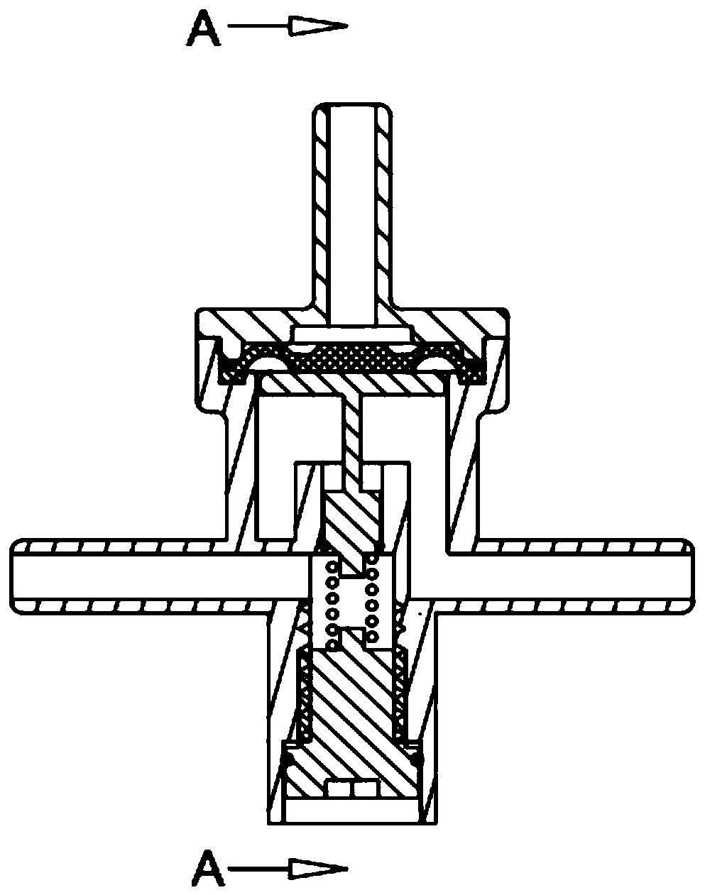
[0035] In this example, if image 3 with Figure 4 As shown, the valve body 2 is provided with a third blocking channel 18 for the concentrated water to enter the drain chamber 3. The valve body 2 has a sealing water port with a structure of the valve body 2 inside the valve body 2, and the sealing water port is located on the third blocking channel 18. During the water production process, the pressure at the clean water inlet 5 is small, so that the concentrated water stays in the concentrated water channel 24 until the water pressure rises and pushes the second diaphragm 23; at this time, the concentrated water passes through the third blocking channel 18 A small amount enters the drain chamber 3; under the fixing action of the outer cover 21, the second spring 20 exerts elastic force on the pressure plate 22 in the opposite direction, so that the second diaphragm 23 can return to block the concentrated water channel 24 and the third blocking channel 18, effectively maintain...


PUM


Abstract

The invention discloses a water purifier system with a flush valve. The water purifier system comprises a first filter group, a second filter group, a water cut-off valve, a booster pump, a large-fluxreverse osmosis filter group and a high-pressure switch, a raw water pipe is sequentially communicated with the first filter group, the water cut-off valve and the second filter group through pipelines; a water outlet of the second filter group is sequentially communicated with the booster pump and the large-flux reverse osmosis filter group through pipelines; the water outlet end of the large-flux reverse osmosis group is communicated with a purified water pipe and a concentrated water pipe, the purified water pipe is communicated with the high-pressure switch, the high-pressure switch is communicated with a purified water faucet, the concentrated water pipe is communicated with a concentrated water inlet of a flush valve, the upper end of the flush valve is communicated with the purified water pipe serially connected with the high-pressure switch purified water faucet, and a water outlet of the flush valve is communicated with a concentrated water drain pipe. And the structure is simple, the size is relatively smaller, the production process is simple, and therefore the input cost is lower.

Description

technical field [0001] The invention relates to the technical field of pure water machines, in particular to a pure water machine system with a flushing valve. Background technique [0002] With the development of the economy, the situation of water resources has deteriorated in many places. The shortage and pollution of water resources have become more and more serious, and the problem of drinking water safety for urban residents has become prominent. Aiming at the secondary pollution of tap water in cities and the persistent presence of harmful substances in tap water due to source water pollution, more and more household water purifiers with reverse osmosis membrane as the core filter unit have entered thousands of households. The existing household pure water machine uses the reverse osmosis membrane as the core filter unit. After multi-stage pretreatment and pressurization of tap water, it enters the reverse osmosis membrane unit. The pure water produced can fully meet ...

Claims


Application Information

Patent Timeline
Patent Type & Authority Applications(China)
IPC IPC(8): C02F9/02
CPCC02F1/001C02F1/441C02F2303/14
Inventor 吴瑞昌
Owner 宁波川渡流体科技有限公司
Why Eureka
Try Eureka