Hydraulic anchor rod drill carriage

A bolt drilling rig and hydraulic technology, applied in the fields of tunnel construction machinery and mines, can solve the problems of heavy propulsion beam and complicated operation, and achieve the effect of continuous rock drilling and anchoring process, good economic benefits and high production efficiency.

Pending Publication Date: 2020-07-14
ZHEJIANG KAISHAN HEAVY IND CO LTD
View PDF8 Cites 6 Cited by
  • Summary
  • Abstract
  • Description
  • Claims
  • Application Information

AI Technical Summary

Problems solved by technology

[0006] 1) Although the drill-bolt switching rate has been improved to a certain extent compared with the original bolt support scheme, there is still room for improvement;
[0007] 2) For rock bolters using double rock drills, two sets of propulsion systems are often used, which makes the propulsion beam very heavy and complicated to operate

Method used


Image

  • Hydraulic anchor rod drill carriage
  • Hydraulic anchor rod drill carriage
  • Hydraulic anchor rod drill carriage

Examples


Embodiment 1

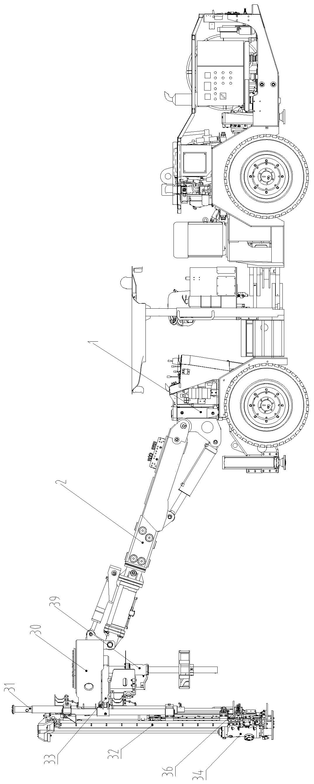
[0046] Such as Figure 1-5 A hydraulic rock bolter is shown, including engineering chassis 1, working arm 2, propulsion beam, electrical system, hydraulic system and driver's cab; wherein, engineering chassis 1 is used to provide support for the whole vehicle to ensure the rigidity of the whole vehicle and strength, the front lateral telescopic form of the outriggers of the engineering chassis 1 can ensure the stability of the whole vehicle, the electrical system and hydraulic system are used to ensure the normal work of the propulsion beam and the working arm 2, and the cab is used to accommodate the driver and is controlled by The driver manipulates the working arm 2 and the propulsion beam to complete the work of underground support; the propulsion beam is installed on the working arm 2 and adjusted to a vertical state through the working arm 2; the improvement is that;

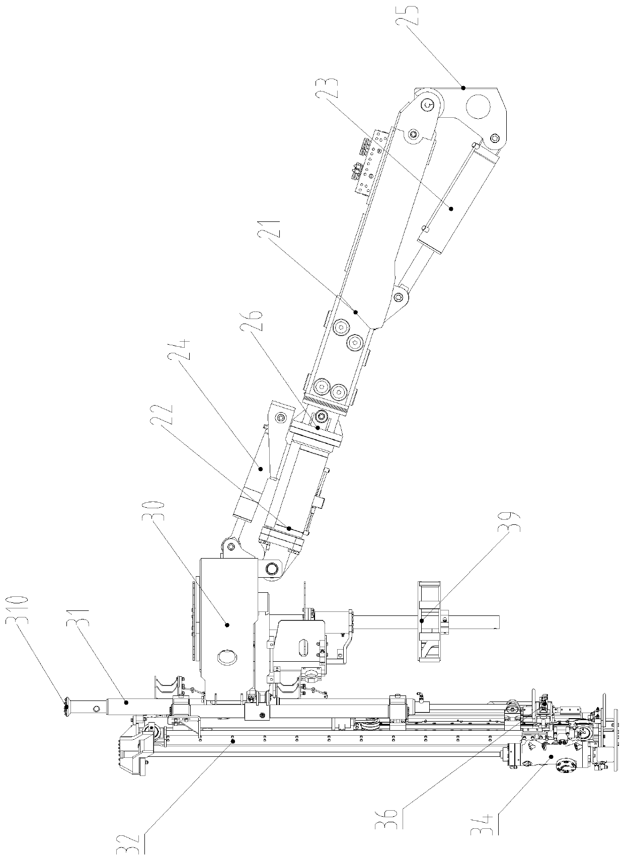
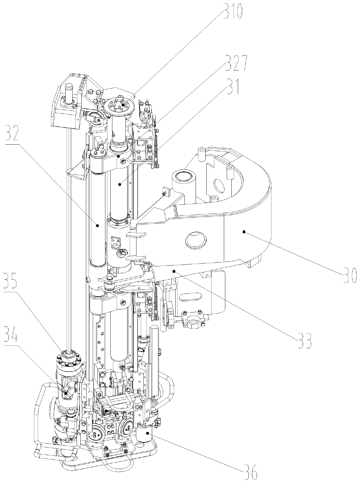
[0047] Such as Figure 2-5 The shown propulsion beam includes a bracket 30 installed on the working ar...

Embodiment 2

[0077] The difference between this embodiment and Embodiment 1 is that in this embodiment there is no limit interlock assembly and interlock cylinder; and a second propulsion cylinder is added; that is, one of the propulsion cylinders is responsible for the lifting of the drilling rock drill The other propulsion cylinder is responsible for the lifting and pulling back of the rock bolter, and the two do not interfere with each other.

[0078] In this embodiment, a propulsion beam includes a bracket installed on the working arm, a fixed beam fixedly installed on the bracket, and a rotating beam rotatably installed on the bracket. The fixed beam and the rotating beam are distributed in parallel, and the rotating beam It is driven by a switching cylinder to rotate with the fixed beam as the central axis; a drilling rock drill and a rock bolter are also installed on the rotating beam, as well as a first propulsion cylinder for pushing the drilling rock drill to move axially, and for...

Embodiment 3

[0089] The difference between this embodiment and Embodiment 1 is that in this embodiment, the switching between the drilling rock drill and the rock bolter is completed by sliding in translation.

[0090] For example, the rotating beam is slidably installed on the fixed beam.


PUM


Abstract

The invention discloses a hydraulic anchor rod drill carriage which comprises a working arm and a propelling beam. The propelling beam comprises a fixed beam and a rotating beam. The fixed beam and the rotating beam are distributed in parallel, and the rotating beam rotates by taking the fixed beam as a center shaft. A drilling gadder, an anchor rod gadder, a limiting interlocking device and a propelling oil cylinder are further mounted on the rotating beam; during drilling, the limiting interlocking device fixes the anchor rod gadder; during anchoring, the limiting interlocking device fixes the drilling gadder; moreover, the top end of the fixed beam leans against a top plate of a roadway needed to be anchored immobile all the time. According to the technical scheme, the drilling gadder and the anchor rod gadder are switched by a rotating mode, so that the drill and anchor switching rate is improved obviously, and furthermore, the work efficiency is improved obviously. In addition, the drilling gadder and the anchor rod gadder can be driven only by one propelling oil cylinder, so that the hydraulic anchor rod drill carriage is simple to operate, the integral cost can be further lowered, and underground shoring mechanization is further popularized favorably.

Description

technical field [0001] The invention relates to the technical field of mine and tunnel engineering machinery, in particular to a hydraulic rock bolter. Background technique [0002] Underground support (roadway support) is mainly used to ease and reduce the movement of surrounding rock, so that the section of the roadway will not be excessively reduced, and at the same time prevent the scattered and damaged surrounding rock from caving; usually, in order to make the roadway support adjust and control Playing an active role in the deformation process of the surrounding rock, the support should be installed before the surrounding rock becomes loose and damaged, so that the support can play a bearing role together with the surrounding rock when the surrounding rock still maintains self-supporting force. [0003] Take bolt support as an example; in the process of bolt support, it is necessary to drill the bolt hole first, and then knock in the bolt; Manual installation of bolts...

Claims


Application Information

Patent Timeline
Patent Type & Authority Applications(China)
IPC IPC(8): E21D20/00E21B15/00E21B7/02
CPCE21B7/02E21B15/00E21B15/003E21D20/003
Inventor 徐雪锋夏剑辉杜标高强胜郑晓辉
Owner ZHEJIANG KAISHAN HEAVY IND CO LTD
Why Eureka
Try Eureka