
Liquid fuel jet engine oxidant drainage equipment

A technology of jet engine and liquid fuel, which is applied in the direction of mechanical equipment, machine/engine, rocket engine device, etc. It can solve the problems of insufficient amount of oxidizer, pollutant discharge, lack of fuel recovery mechanism, etc.

Inactive Publication Date: 2020-07-14
朱凤梅
View PDF0 Cites 1 Cited by
  • Summary
  • Abstract
  • Description
  • Claims
  • Application Information

AI Technical Summary

Problems solved by technology

[0003] Wherein the fuel of the liquid fuel engine needs to use oxidant when burning, and the prior art adopts the mode of fixed injection for the introduction of oxidant, can not carry out proper amount of oxidizer according to the amount of ignited fuel oil, causes fuel to burn insufficiently and forms pollutant to be discharged; In addition, the existing fuel spraying equipment lacks a fuel recovery mechanism, resulting in waste of unburned fuel, so a liquid fuel jet engine diversion oxidant equipment came into being

Method used


Image

  • Liquid fuel jet engine oxidant drainage equipment
  • Liquid fuel jet engine oxidant drainage equipment
  • Liquid fuel jet engine oxidant drainage equipment

Examples


Embodiment Construction

[0023] The following will clearly and completely describe the technical solutions in the embodiments of the present invention with reference to the accompanying drawings in the embodiments of the present invention. Obviously, the described embodiments are only some, not all, embodiments of the present invention. Based on the embodiments of the present invention, all other embodiments obtained by persons of ordinary skill in the art without making creative efforts belong to the protection scope of the present invention.

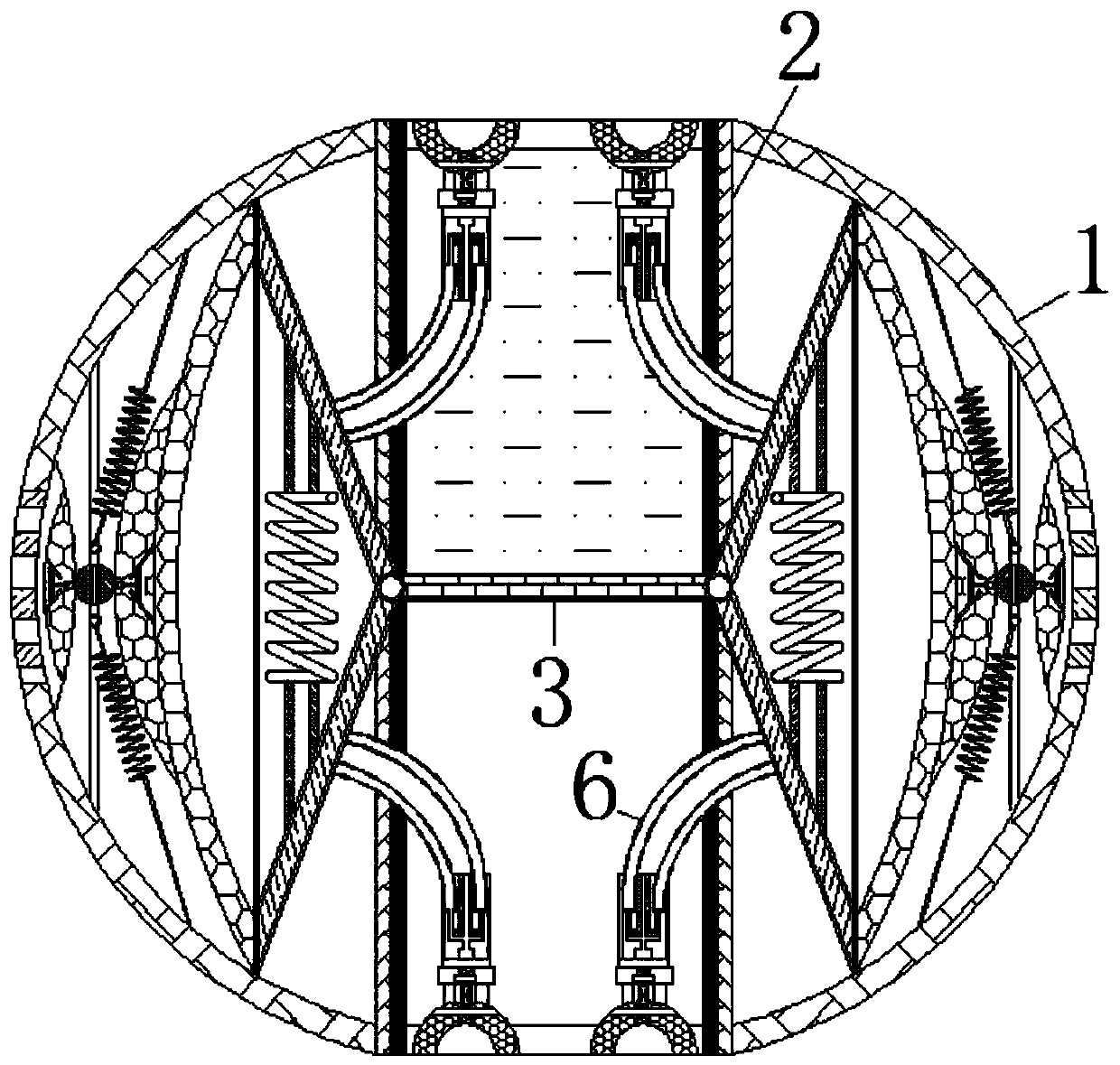
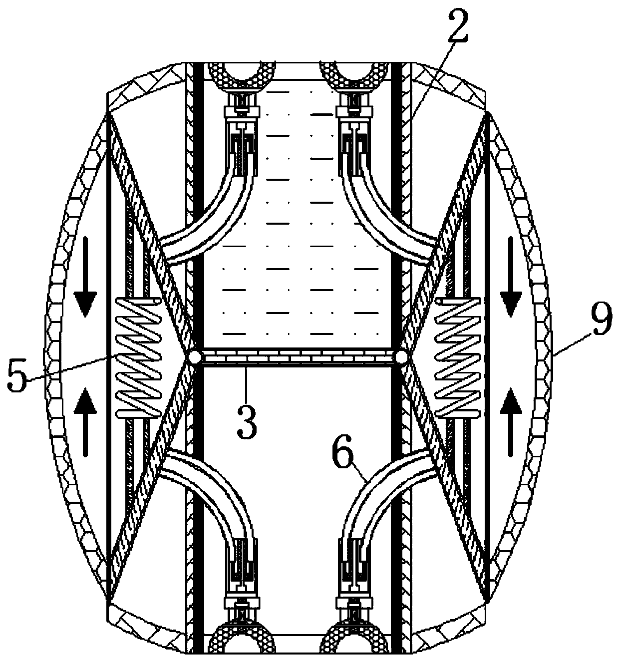
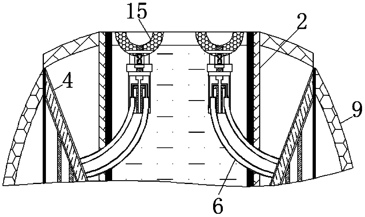
[0024] see Figure 1-7 , a liquid fuel jet engine diversion oxidant equipment, including a housing 1, the inside of the housing 1 is provided with a chute 2, the surface of the chute 2 is slidably connected with a bearing plate 3, and the space formed by the chute 2 and the bearing plate 3 is Liquid flow channel; the surface of the bearing plate 3 is provided with a liquid flow port, and the surface of the liquid flow port is fixedly connected with a pressure ...


PUM


Abstract

The invention relates to the technical field of jet engines, and discloses liquid fuel jet engine oxidant drainage equipment. The liquid fuel jet engine oxidant drainage equipment comprises a shell, asliding groove is formed inside the shell, a bearing plate is slidably connected to the surface of the sliding groove, a telescopic rod is movably connected to the surface of the bearing plate, a contraction spring is movably connected to the surface of the telescopic rod, a flexible pipe is fixedly connected to the side, away from the contraction spring, of the telescopic rod, a drainage pipe isfixedly connected to the surface of the flexible pipe, a spring rod is movably connected into the drainage pipe, an elastic bag is fixedly connected to the end, away from the bearing plate, of the telescopic rod, a reset spring is movably connected to the surface of the elastic bag, a liquid storage bag is movably connected into the elastic bag, and the surface of the liquid storage bag is movably connected with an extrusion rod. A negative pressure bag at the lower part generates suction force to suck back oil liquid dripped and hung at the bottom of the shell and store the oil liquid in animpurity storage tank, so that the effect of recovering the unburned liquid or atomized fuel is achieved.

Description

technical field [0001] The invention relates to the technical field of jet engines, in particular to a liquid fuel jet engine drainage oxidizer device. Background technique [0002] Jet engine refers to the engine that directly generates reaction thrust by jetting out the air at high speed through the nozzle, and is widely used as a power plant for aircraft; its principle is that fuel and oxidant react chemically in the combustion chamber of the engine to release heat energy, and then the heat energy is released in the nozzle. Converted into the function of adjusting airflow, jet engines are divided into solid fuel engines and liquid fuel engines according to different fuels. [0003] Wherein the fuel of the liquid fuel engine needs to use oxidant when burning, and the prior art adopts the mode of fixed injection for the introduction of oxidant, can not carry out proper amount of oxidizer according to the amount of ignited fuel oil, causes fuel to burn insufficiently and for...

Claims


Application Information

Patent Timeline
IPC IPC(8): F02K9/46F02K9/56F04B45/00
CPCF02K9/46F02K9/563F04B45/00
Inventor 朱凤梅
Owner 朱凤梅
Learn More