Airway management series device used after tracheotomy

A tracheotomy and airway technology, applied in the direction of tracheal intubation, etc., can solve the problems of the inner cannula not having an anti-reflux structure, increasing the workload of clinical nursing, and the inability of medicinal liquid to reach the lungs, etc. Burden, reduced risk of wound infection, effect of simple structure

Active Publication Date: 2020-07-17
SHANGHAI NINTH PEOPLES HOSPITAL SHANGHAI JIAO TONG UNIV SCHOOL OF MEDICINE
View PDF6 Cites 2 Cited by
  • Summary
  • Abstract
  • Description
  • Claims
  • Application Information

AI Technical Summary

Problems solved by technology

When clinical nurses are nebulizing patients, there are the following problems when using the mask method for aerosol inhalation: first, a large amount of medicinal liquid cannot reach the lungs to produce curative effect, and second, it causes a large amount of medicinal liquid to be wasted
In autumn and winter, some patients have viscous sputum and easy to produce sputum scabs, which require continuous humidification. Currently, existing devices require nurses to administer medication frequently, which also increases the workload of clinical nursing.
[0007] In addition, for the treatment of patients' sputum, the existing method is often to connect a collection bag for collecting sputum on the back side of the inner cannula. However, since the inner cannula does not have an anti-reflux structure, once the sputum goes backward, Risk of severe lung infection and related complications in patients
Moreover, when the patient coughs, the sputum will be sprayed out from the endotracheal intubation port with a large impact force, which is likely to cause long-distance pollution, and the pollution covers a large area

Method used


Image

  • Airway management series device used after tracheotomy
  • Airway management series device used after tracheotomy
  • Airway management series device used after tracheotomy

Examples


specific Embodiment 1

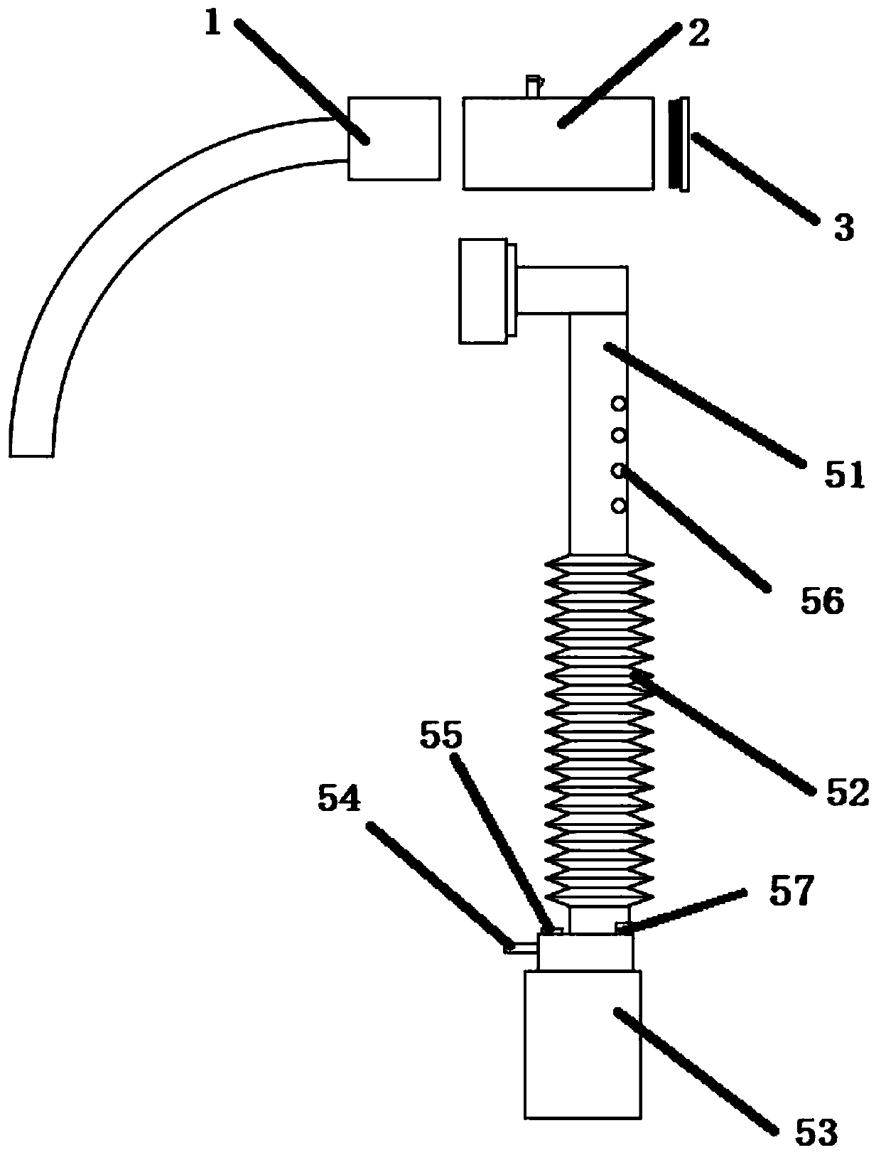
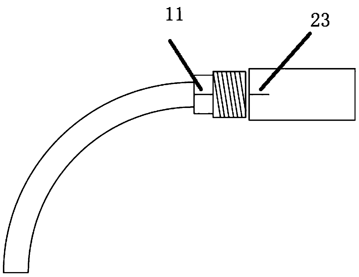
[0093] Specific embodiment 1, see figure 1 , a series of airway management devices after tracheotomy, including a post-tracheotomy intubation tube, the post-tracheotomy intubation tube includes an outer tube and an inner tube 1 .

[0094] It also includes a humidification structure, which includes sequentially connected airway joints 52, threaded extension tubes 52, and atomization tanks 53; the airway joints are detachably connected to the rear end of the inner sleeve 1, and the airway joints are provided with gas exchange Hole 56; a rubber stopper 55 for temporary injection of medicinal solution is installed on one side of the atomizer tank top, and a dosing hole 57 for continuous infusion of medicinal solution is installed on the other side, and the top of the dosing hole is covered with plastic The cover, and an oxygen conduit interface 54 is arranged on one side of the upper middle part of the atomization tank. Threaded extensions can be bellows.

[0095] It also includ...

specific Embodiment 2

[0105] Specific embodiment 2, on the basis of specific embodiment 1, refer to Image 6 , the outer side of the threaded extension tube is detachably installed with a setting mechanism; the setting mechanism includes a first collar 41 and a second collar 42 sleeved on the periphery of the threaded extension tube; the first collar 41 and the second collar 42 pass through a can The bent metal rod 43 is connected; the first collar and the second collar are also connected by two connecting parts, and the connecting part includes a first connecting rod 44, a spring 45 and a second connecting rod 46 connected in sequence; the metal rod 43 and the second connecting rod All connecting rods are arranged along the circumferential direction. It is convenient to realize the bending and setting of the threaded extension pipe. Furthermore, the atomization can is placed on the shoulder of the patient, and the pulling caused by the atomization can at the interface is reduced.

specific Embodiment 3

[0106] Specific embodiment 3, on the basis of specific embodiment 1, refer to Figure 7 A caliber adjustment sleeve 7 is slidably connected to the standpipe, and the caliber adjustment sleeve includes an annular baffle 72 whose axial width is not less than the inner diameter of the gas exchange port. It is convenient to realize the organic adjustment of the caliber. The caliber adjusting sleeve includes a mounting cylinder, which is connected with the annular baffle through a connecting strip. Adjacent ring-shaped baffles are connected by connecting bars. The installation cylinder and the standpipe are connected by threads. The outer wall of the standpipe is provided with a scale mark for marking the adjustment of the caliber. There is a reference line for aligning the scale line on the installation cylinder. It is convenient to realize the adjustment of different diameters during the relative rotation of the installation cylinder and the standpipe.

[0107] Of course, th...


PUM


Abstract

The invention relates to the field of tracheal cannula nursing supplies. An airway management series device used after tracheotomy comprises an airway cannula used after tracheotomy; the airway cannula comprises an outer sleeve and a matched inner sleeve, and also comprises a humidifying structure, wherein the humidifying structure comprises an airway joint, a threaded extension pipe and an atomizing tank which are sequentially connected; the airway joint is detachably connected with the outer end of the inner sleeve; a gas exchange hole is formed in the airway joint; a rubber plug for temporarily injecting liquid medicines is arranged in one side of the top of the atomizing tank; a medicine adding hole for continuously infusing the liquid medicines is arranged in the other side of the topof the atomizing tank; an oxygen conduit interface is arranged on one side of the middle part of the atomizing tank; the airway cannula also comprises an anti-reverse flow valve, wherein the rear endof the inner sleeve is detachably connected with the anti-reverse flow valve; the anti-reverse flow valve comprises a valve body and an anti-reverse flow limiting piece arranged in the valve body; the rear side of the valve body is in threaded connection with a sealing plug. The airway joint and the inner cannula are detachable, so that the problem that an atomizing device on the market at present is not matched with a tracheal intubation joint is solved.

Description

technical field [0001] The invention relates to the field of tracheal tube care products, in particular to an airway management device after tracheotomy. Background technique [0002] Tracheotomy is an emergency technique for rescuing critically ill patients, and it can improve dyspnea caused by various reasons after operation. It is an operation in which the front wall of the trachea in the neck is cut open, and an endotracheal tube of appropriate size is inserted into the trachea through the incision, so that the patient can breathe directly through the endotracheal tube. [0003] The purpose of tracheotomy is to prevent or quickly relieve airway obstruction, ensure unobstructed airway, ensure effective ventilation, and improve breathing. [0004] After the tracheotomy, a dedicated post-tracheotomy tube must be inserted into the patient's trachea. A conventional post-tracheostomy tube includes an outer tube and an inner tube inserted into the outer tube, the outer tube h...

Claims


Application Information

Patent Timeline
Patent Type & Authority Applications(China)
IPC IPC(8): A61M16/04
CPCA61M16/04
Inventor 侯黎莉王悦平李丽徐诸凤蒋莉莉
Owner SHANGHAI NINTH PEOPLES HOSPITAL SHANGHAI JIAO TONG UNIV SCHOOL OF MEDICINE
Why Eureka
Try Eureka