Chemical reaction kettle
A chemical reaction and kettle cover technology, applied in the field of chemical reactor cleaning, can solve problems such as increasing the difficulty of cleaning and increasing the difficulty of operation by staff, and achieves the effect of convenient and fast cleaning process and improved cleaning efficiency
- Summary
- Abstract
- Description
- Claims
- Application Information
AI Technical Summary
Problems solved by technology
Method used
Image
Examples
specific Embodiment approach 1
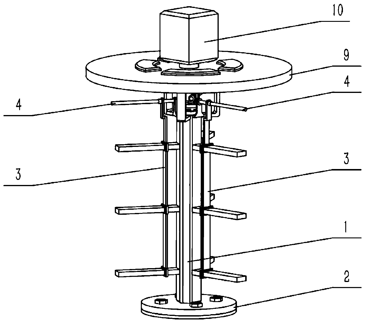
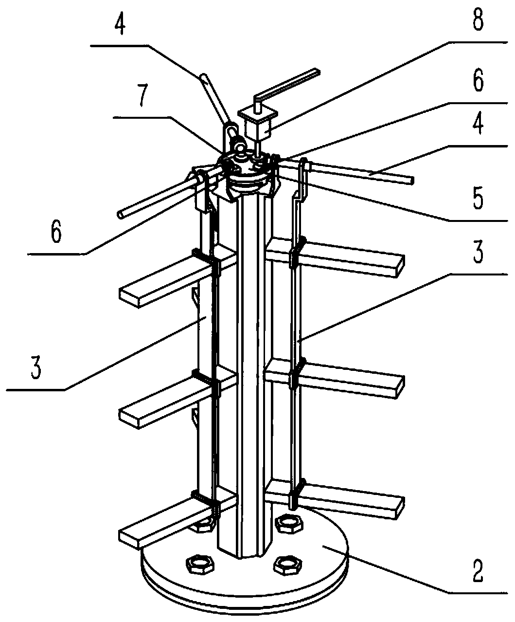
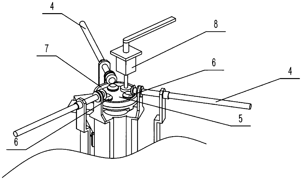
[0038] Combine below Figure 1-14 Description of this embodiment, a chemical reaction kettle, including a stirring group 1 and a base 2, the base 2 is fixedly connected to the bottom wall of the stirred tank body, and the lower end of the stirring group 1 is rotatably connected to the middle of the base 2 , the chemical reaction kettle also includes a cleaning plate 3, a transmission rod 4, a connecting seat 5, a transmission gear set 6, a transmission ring gear set 7, a cleaning motor 8, a kettle cover 9 and a stirring drive mechanism 10, and the cleaning plate 3 is provided with A plurality of cleaning plates 3 are respectively slidably connected to each stirring paddle 1-1 on the peripheral side of the stirring group 1, and the transmission rod 4 is provided with a plurality, and the inner ends of the plurality of transmission rods 4 are uniform in the circumferential direction. Rotationally connected to the upper end of the stirring group 1, the upper ends of a plurality of ...
specific Embodiment approach 2
[0040] Combine below Figure 1-14 Describe this embodiment, this embodiment will further explain Embodiment 1, a plurality of stirring paddles 1-1 are uniformly arranged on the stirring group 1, and a drum 1-2 is arranged on the upper end thereof, and the transmission ring gear set 7 The lower end of the rotating drum 1-2 is rotatably connected, the upper end of the stirring group 1 is evenly provided with a plurality of positioning plates 1-3 in the circumferential direction, and the inner ends of the plurality of transmission rods 4 are respectively rotatably connected to the plurality of positioning plates 1-3. 3, the upper end of the stirring group 1 is provided with a plurality of connection plates 1-4, the lower part of the stirring drive mechanism 10 is fixedly connected with the plurality of connection plates 1-4, and the lower end of the stirring group 1 is provided with a rotating shaft 1-5, so The rotating shaft 1-5 is rotatably connected to the base 2, and the inne...
specific Embodiment approach 3
[0042] Combine below Figure 1-14 Describe this embodiment, this embodiment will further explain Embodiment 1, the cleaning plate 3 is provided with a plurality of slide frames 3-1 corresponding to each stirring blade 1-1, and a cleaning frame is provided outside the slide frame 3-1 3-2, the sliding frame 3-1 is slidably connected to the corresponding stirring paddle 1-1, the upper end of the cleaning plate 3 is provided with a threaded pipe 3-3, and the transmission rod 4 is connected to the corresponding threaded pipe through threaded transmission Within 3-3.
PUM
 Abstract
Description
Claims
Application Information
 - R&D Engineer
- R&D Manager
- IP Professional
- Industry Leading Data Capabilities
- Powerful AI technology
- Patent DNA Extraction
Browse by: Latest US Patents, China's latest patents, Technical Efficacy Thesaurus, Application Domain, Technology Topic, Popular Technical Reports.
© 2024 PatSnap. All rights reserved.Legal|Privacy policy|Modern Slavery Act Transparency Statement|Sitemap|About US| Contact US: help@patsnap.com


