
Die device

A technology for molds and mold bases, which is applied in the field of mold devices, can solve the problems of taking a long time to lift molds, water seepage or water leakage, and increased repair time, so as to reduce the probability of water seepage or water leakage, reduce the occupied space, and improve the use The effect of longevity

Pending Publication Date: 2020-07-17
YANGXIN TECH SUZHOU
View PDF5 Cites 2 Cited by
  • Summary
  • Abstract
  • Description
  • Claims
  • Application Information

AI Technical Summary

Problems solved by technology

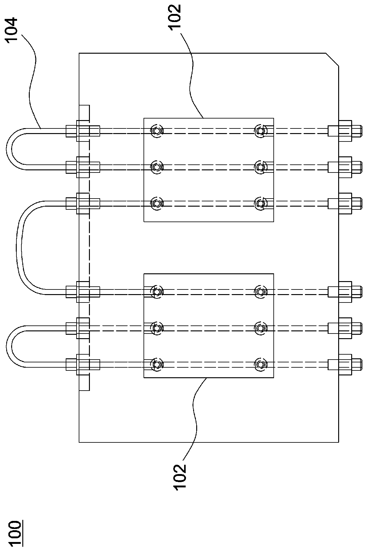
like figure 1 As shown, when the number of mold cavities 102 of the mold device 100 increases, there will be more external water pipes 104, which will easily cause damage to the external water pipes 104 during the process of water pipe disassembly, transportation, and upper and lower molds, resulting in water seepage or water leakage. If water seepage or leakage is detected in time, the mold core will form water stains, rust spots or even rust damage when exposed to moisture for a period of time, resulting in increased repair time and expensive repair costs
Furthermore, because the external water pipe is exposed, it takes a long time to raise and lower the temperature of the mold, and cannot provide stable mold temperature control

Method used


Image

  • Die device
  • Die device
  • Die device

Examples


Embodiment Construction

[0015] The aforementioned and other technical contents, features and effects of the present invention will be clearly presented in the following detailed description of the embodiments with reference to the accompanying drawings. The directional terms mentioned in the following embodiments, such as: up, down, left, right, front or back, etc., are only referring to the directions of the drawings. Accordingly, the directional terms are used to illustrate and not to limit the invention.

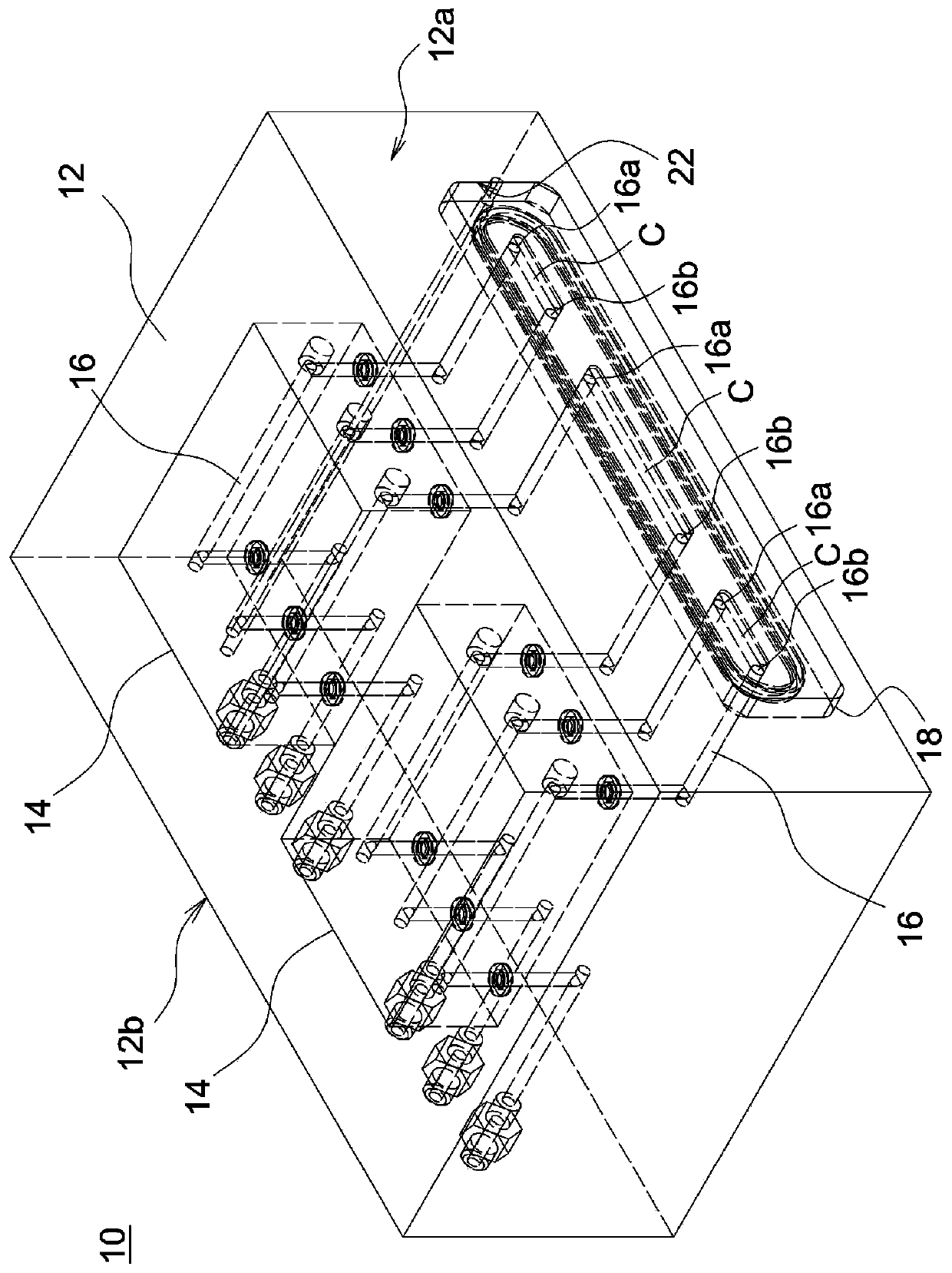
[0016] figure 2 It is a schematic diagram of a mold device according to an embodiment of the present invention. Please refer to figure 2 , in this embodiment, the mold device 10 includes a mold base 12 , at least one mold core 14 , a plurality of fluid pipelines 16 and at least one deflector 18 . The mold core 14 can be used, for example, to form a light guide plate. The mold base 12 has a first side 12 a and a second side 12 b opposite to each other, and a groove 22 is formed on the first ...


PUM


Abstract

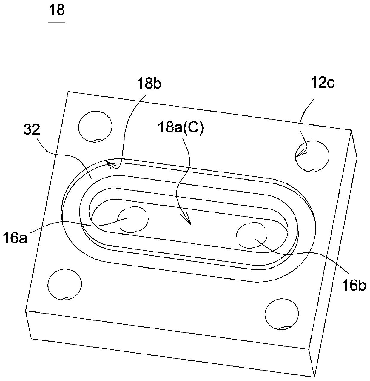
The invention provides a die device. The die device comprises a die holder, at least one die core, a plurality of fluid pipelines and at least one guide plate, wherein the die holder is provided witha first side and a second side which are opposite to each other, a groove is formed in the first side of the die holder, and the die core is arranged between the first side and the second side; the fluid pipelines are arranged on the die holder in a penetrating mode to generate fluid circulation changing the temperature of the die core, and the ends, corresponding to the first side, of the fluid pipelines are positioned in the groove; and the guide plate is fixed to the die holder, at least one flow channel is defined by the guide plate and the first side of the die holder, and the ends, corresponding to the first side, of the fluid pipelines communicate with the flow channel.

Description

technical field [0001] The present invention relates to a mold device. Background technique [0002] In the current injection molding process of light guide plates, multi-cavity molds are often used to improve production efficiency. However, in the design of one mold with two or more mold cavities, it is necessary to control the mold temperature stably and avoid the problem of water overflow or leakage of the cooling water pipe. figure 1 The liquid circulation system design of a known mold assembly is shown. like figure 1 As shown, when the number of mold cavities 102 of the mold device 100 increases, there will be more external water pipes 104, which will easily cause damage to the external water pipes 104 during the process of water pipe disassembly, transportation, and upper and lower molds, resulting in water seepage or water leakage. If water seepage or water leakage is detected in time, the mold core will form water stains and rust spots or even rust damage when exp...

Claims


Application Information

Patent Timeline
Patent Type & Authority Applications(China)
IPC IPC(8): B29C45/73
CPCB29C45/7312
Inventor 郭明刚徐嘉宏于立新王征辉
Owner YANGXIN TECH SUZHOU
Learn More