Heat pipe heat dissipation system for automobile LED lamp

A technology of LED lamps and heat dissipation systems, applied in the direction of headlamps, cooling/heating devices of lighting devices, motor vehicles, etc., can solve the problems of increasing cost, increasing the volume of radiators, changing the effect of heat dissipation, etc., and prolonging the service life. , the effect of improving the transfer rate and reducing the volume

Pending Publication Date: 2020-07-17
GUILIN UNIV OF ELECTRONIC TECH
View PDF0 Cites 0 Cited by
  • Summary
  • Abstract
  • Description
  • Claims
  • Application Information

AI Technical Summary

Problems solved by technology

The effect of these improvements on heat dissipation is extremely small, and even in the case of increasing the cost and increasing the volume of the radiator, only a very small effect is finally achieved.

Method used


Image

  • Heat pipe heat dissipation system for automobile LED lamp
  • Heat pipe heat dissipation system for automobile LED lamp

Examples


Embodiment Construction

[0018] The principles and features of the present invention are described below in conjunction with the accompanying drawings, and the examples given are only used to explain the present invention, and are not intended to limit the scope of the present invention.

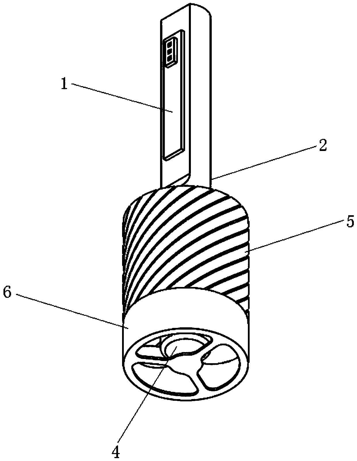
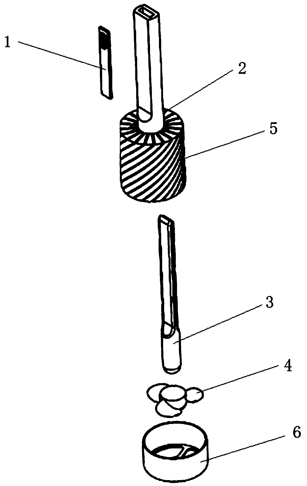
[0019] like figure 1 and 2 As shown, a heat pipe cooling system for automotive LED lamps includes an LED substrate 1 , a heat dissipation housing 2 , a heat pipe 3 and a micro fan 4 . The LED substrate 1 is pasted on the outer wall of the front part of the heat dissipation housing 2, on which LED lamp beads are arranged. The front end of the heat pipe 3 is in the front of the heat dissipation housing 2, and its rear end extends in the heat dissipation housing 2 to the tail of the heat dissipation housing 2 to transfer the heat generated by the LED lamp beads to the rear. Preferably: the front part of the heat pipe 3 is flat, and the rear part is columnar to facilitate processing and assembly into the heat dissipat...


PUM


Abstract

The invention relates to a heat pipe heat dissipation system for an automobile LED lamp. The heat pipe heat dissipation system comprises an LED substrate, a heat dissipation shell, a heat pipe and a micro fan. The LED substrate is attached to the outer side wall of the front portion of the heat dissipation shell, and LED lamp beads are arranged on the LED substrate. The front end of the heat pipeis located in the front portion of the heat dissipation shell, and the rear end of the heat pipe extends to the tail portion of the heat dissipation shell in the heat dissipation shell. The micro fanis positioned in the tail part of the heat dissipation shell; a chip for controlling the rotating speed of the micro fan by sensing the temperature of the LED lamp beads is further arranged on the LEDsubstrate; and the tail portion of the heat dissipation shell is of a fin structure. The heat pipe heat dissipation system has the beneficial effects that: 1, a pipe heat dissipation technology is applied, and a heat dissipation mode of combining a heat pipe, a fan and fins is adopted, so that the heat transfer rate is greatly improved; 2, a temperature feedback adjusting system is additionally arranged, so that different rotating speeds of the miniature fan at different temperatures of the lamp body can be realized; and 3, favorable conditions are provided for replacing the existing productin the later period.

Description

technical field [0001] The invention relates to the field of automobile lighting heat dissipation, in particular to a heat pipe heat dissipation system for automobile LED lamps. Background technique [0002] LED is the most promising new cold light source in the 21st century. Compared with traditional light sources, it has the advantages of high efficiency, fast response, pure light color, and low energy consumption. In recent years, it has been gradually applied to aerospace, military, ships, and vehicles. , Civil lighting and other fields. With the development of LED, more and more car manufacturers have adopted LED lights as the first choice for headlights. At present, the heat dissipation methods of automotive LED lights on the market are mainly fin heat dissipation, fin heat dissipation, braided belt heat dissipation, and fan heat dissipation. . [0003] There are many kinds of heat dissipation methods for automotive LED lights, which are dazzling. Among them, the mai...

Claims


Application Information

Patent Timeline
Patent Type & Authority Applications(China)
IPC IPC(8): F21S41/141F21S45/43F21S45/46F21V19/00F21V23/00F21V29/503F21V29/51F21W107/10F21Y115/10
CPCF21S41/141F21S45/43F21S45/46F21V19/001F21V23/00F21V29/503F21V29/51F21W2107/10F21Y2115/10
Inventor 贾宝阳梁才航蔡法星郑嘉欣
Owner GUILIN UNIV OF ELECTRONIC TECH
Why Eureka
Try Eureka