
Model correction method and device suitable for elastic connection structure

An elastic connection and model correction technology, applied in design optimization/simulation, etc., can solve problems such as no corresponding dynamic model, low calculation efficiency, and inability to carry out analysis

Pending Publication Date: 2020-07-17
BEIJING INST OF ELECTRONICS SYST ENG
View PDF4 Cites 1 Cited by
  • Summary
  • Abstract
  • Description
  • Claims
  • Application Information

AI Technical Summary

Problems solved by technology

[0003] 1. In the development process, it is often necessary to optimize the design of the parameters of the elastic connection (such as connection stiffness, connection damping, etc.). Using traditional finite element analysis, the finite element calculation of the entire model needs to be carried out for each parameter adjustment, and the calculation efficiency is low. , the influence of parameters is not direct. When the finite element analysis software itself does not have the optimization function, it cannot carry out automatic optimization design, and can only rely on manual calculation
[0004] 2. There are often nonlinear links in the connection link of the structure, such as the folding clearance of the folding rudder surface, the transmission clearance of the transmission mechanism, the nonlinear damping of the equipment installation support, etc. These features generally have no corresponding dynamics in the finite element software model, it is impossible to carry out relevant analysis
[0005] 3. In engineering development, it is necessary to correct the dynamic model according to the results of the modal test, and to test the stiffness of the elastic connection according to the modal frequency. The direct analysis of the finite element method requires multiple analyzes, which requires a large amount of calculation and indirect influence of parameters, etc. Problems make engineering development inefficient

Method used


Image

  • Model correction method and device suitable for elastic connection structure
  • Model correction method and device suitable for elastic connection structure
  • Model correction method and device suitable for elastic connection structure

Examples


Embodiment Construction

[0058] The following will clearly and completely describe the technical solutions in the embodiments of the present invention with reference to the accompanying drawings in the embodiments of the present invention. Obviously, the described embodiments are only some, not all, embodiments of the present invention. Based on the embodiments of the present invention, all other embodiments obtained by persons of ordinary skill in the art without making creative efforts belong to the protection scope of the present invention.

[0059] Embodiments of the present invention provide a model correction method suitable for elastic connection structures, such as Figure 8 shown, including:

[0060] S1: Split the structure connected by the elastic connection structure into multiple different substructures;

[0061] S2: Establish a dynamic model of each substructure;

[0062] S3: Generate a coupled overall dynamic model according to the mass matrix and stiffness matrix in each substructure ...


PUM


Abstract

The invention provides model correction method and device suitable for an elastic connection structure. According to the method, a kinetic analysis model with a linear or nonlinear elastic connectionlink structure can be established. The most important advantage of the technology is that the connection rigidity can be explicitly expressed in an analytical equation; when connection parameters arechanged, kinetic analysis can be directly carried out, large-scale finite element calculation does not need to be carried out again, accordingly parameter design and dynamic response analysis can be carried out rapidly and efficiently, model parameter rapid correction can be carried out on the basis of an overall modal test of an elastic connection structure, and a kinetic model consistent with atest result is obtained.

Description

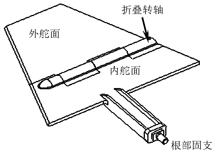
technical field [0001] The invention relates to the field of dynamic model analysis of connection structures, and more specifically, relates to a model correction method and device suitable for elastic connection structures. Background technique [0002] In the actual structure of aerospace, there are often structures with elastic connection links. For example, there is torsional stiffness at the folding axis of the folding rudder surface; there is connection stiffness in the steering gear transmission mechanism; there is elastic support at the installation interface between equipment and brackets. In the existing conventional analysis, the method of finite element analysis is mainly used to carry out dynamic analysis. In this method, the overall finite element model of the structure needs to be established, and the connection link is simulated by spring elements, and then the overall finite element model is analyzed to obtain dynamic properties. There are three problems in...

Claims


Application Information

Patent Timeline
IPC IPC(8): G06F30/23
CPCY02T90/00
Inventor 杨宁
Owner BEIJING INST OF ELECTRONICS SYST ENG
Learn More