Battery cell connector for battery cells connected in series

A battery cell and series connection technology, which is applied in the field of battery cell connectors used to connect battery cells in series, can solve the problems of limiting and limiting the power capacity of the battery system, and achieve the effect of small temperature difference and high thermal reliability

Pending Publication Date: 2020-07-21
ROBERT BOSCH GMBH
View PDF0 Cites 1 Cited by
  • Summary
  • Abstract
  • Description
  • Claims
  • Application Information

AI Technical Summary

Problems solved by technology

However, even such a cooling system is limited at high loads and limits the power capability of the battery system in that the system must be throttled periodically in order to avoid overheating

Method used


Image

  • Battery cell connector for battery cells connected in series
  • Battery cell connector for battery cells connected in series
  • Battery cell connector for battery cells connected in series

Examples


Embodiment Construction

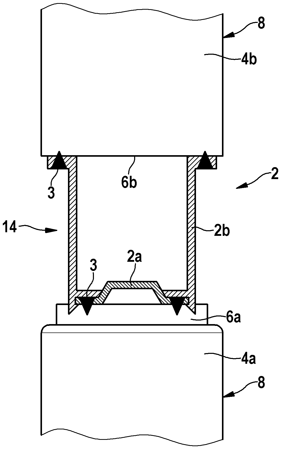
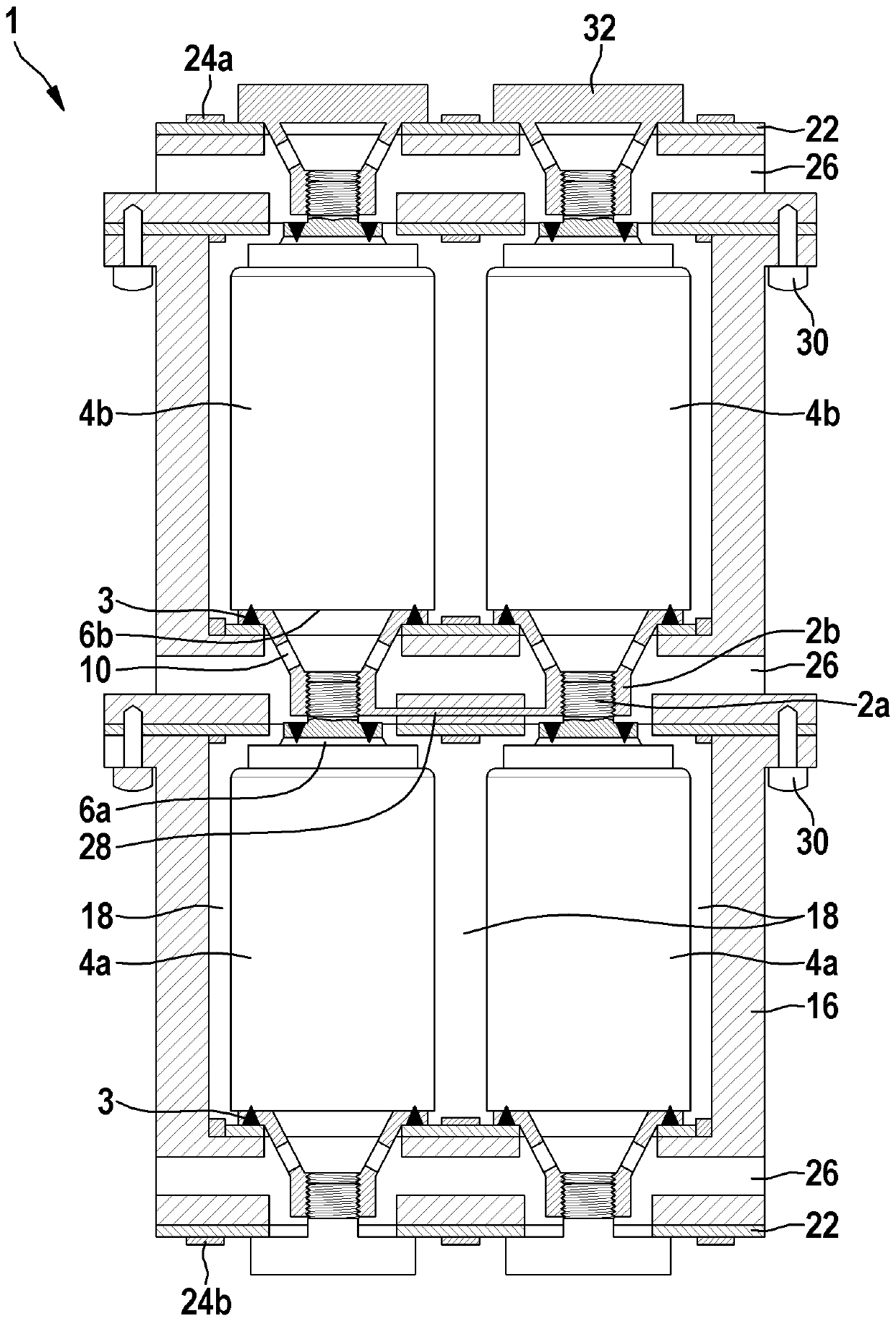
[0027] figure 1 A schematic diagram of a battery cell connector 2 according to the invention for connecting battery cells 4 in series according to a first embodiment is shown in a sectional view. In this case, the battery cell connector 2 comprises a first connection element 2a for establishing a connection to a first battery pole 6a of a first battery cell 4a and a second connection element 2a for establishing a connection to a second battery cell 4b. The second connection element 2b of the connection of the battery pole 6b, wherein the connection elements 2a, 2b are designed in a form-corresponding manner relative to one another and are connected in series with one another in such a way that the contact area 8 surrounding the battery cells 4 can be maximized. In order to ensure effective cooling of the battery cell 4. Here, the connecting elements 2 a and 2 b of the two-part battery cell connector 2 are connected to one another in a force-locking manner. For this purpose, ...


PUM


Abstract

The invention relates to a battery cell connector (2) for battery cells (4) connected in series. The battery cell connector includes a first connecting element (2a) for establishing a connection witha first battery pole (6a) of a first battery cell (4a), and a second connecting element (2b) for establishing a connection with a second battery pole (6b) of a second battery cell (4b). The connectingelements (2a, 2b) are constructed corresponding to each other's shapes and can be connected in series with each other so that a contact surface (8) surrounding the battery cells (4) can be maximizedto ensure effective cooling of the battery cells (4).

Description

technical field [0001] The invention relates to an apparatus of the type according to the independent device claim, a system of the type according to the independent system claim and a method of the type according to the independent method claim. Background technique [0002] Today's electric and hybrid vehicles run on high energy or high power batteries. In order to achieve a satisfactory power supply and service life, the battery must be operated within a narrow temperature range. For this purpose, the battery system must be cooled accordingly by means of an effective cooling system. In the case of high power requirements and / or high ambient temperatures, especially liquid cooling concepts have proven to be particularly suitable here. However, even such cooling systems are limited at high loads and limit the power capability of the battery system in that the system must be throttled periodically in order to avoid overheating. Contents of the invention [0003] Accordi...

Claims


Application Information

Patent Timeline
IPC IPC(8): H01M2/20H01M2/22H01M2/10H01M10/613H01M10/625H01M10/6556H01M10/6567H01M50/528H01M50/213H01M50/35H01M50/51H01M50/517
CPCH01M10/613H01M10/625H01M10/6556H01M10/6567H01M50/528H01M50/51H01M50/517H01M50/35H01M50/213Y02E60/10H01M50/529
Inventor A.伊姆雷
Owner ROBERT BOSCH GMBH
Why Eureka
Try Eureka