Bifurcation bracket

A bifurcation and branching technology, applied in the field of bifurcated stents, can solve the problems of wall thrombus falling off, sparse mesh, treatment, etc., and achieve the effect of increasing the contact area, increasing the supporting force, and facilitating the treatment.

Pending Publication Date: 2020-07-24
HANGZHOU WEIQIANG MEDICAL TECH CO LTD
View PDF8 Cites 3 Cited by
  • Summary
  • Abstract
  • Description
  • Claims
  • Application Information

AI Technical Summary

Problems solved by technology

Among them, conventional straight-tube treatment requires more than one stent (such as a covered stent or a bare stent) to be placed in parallel, or placed crosswise, and the stent is implanted in this way, resulting in the guide wire being unable to use the "mountain-climbing technique" from the femoral artery. After crossing the aortoiliac bifurcation into the contralateral limb vessel, the treatment of the contralateral limb vessel cannot be performed
In addition, after some existing bifurcated stents are implanted at the bifurcation of the abdominal aorta and iliac artery, because the mesh of the bifurcated stent in the bifurcation area is sparse, the mural thrombus at the bifurcation of the abdominal aorta is easy to The bifurcated area of ​​the stent breaks off and enters the circulatory system with the blood

Method used


Image

  • Bifurcation bracket
  • Bifurcation bracket
  • Bifurcation bracket

Examples


no. 1 approach

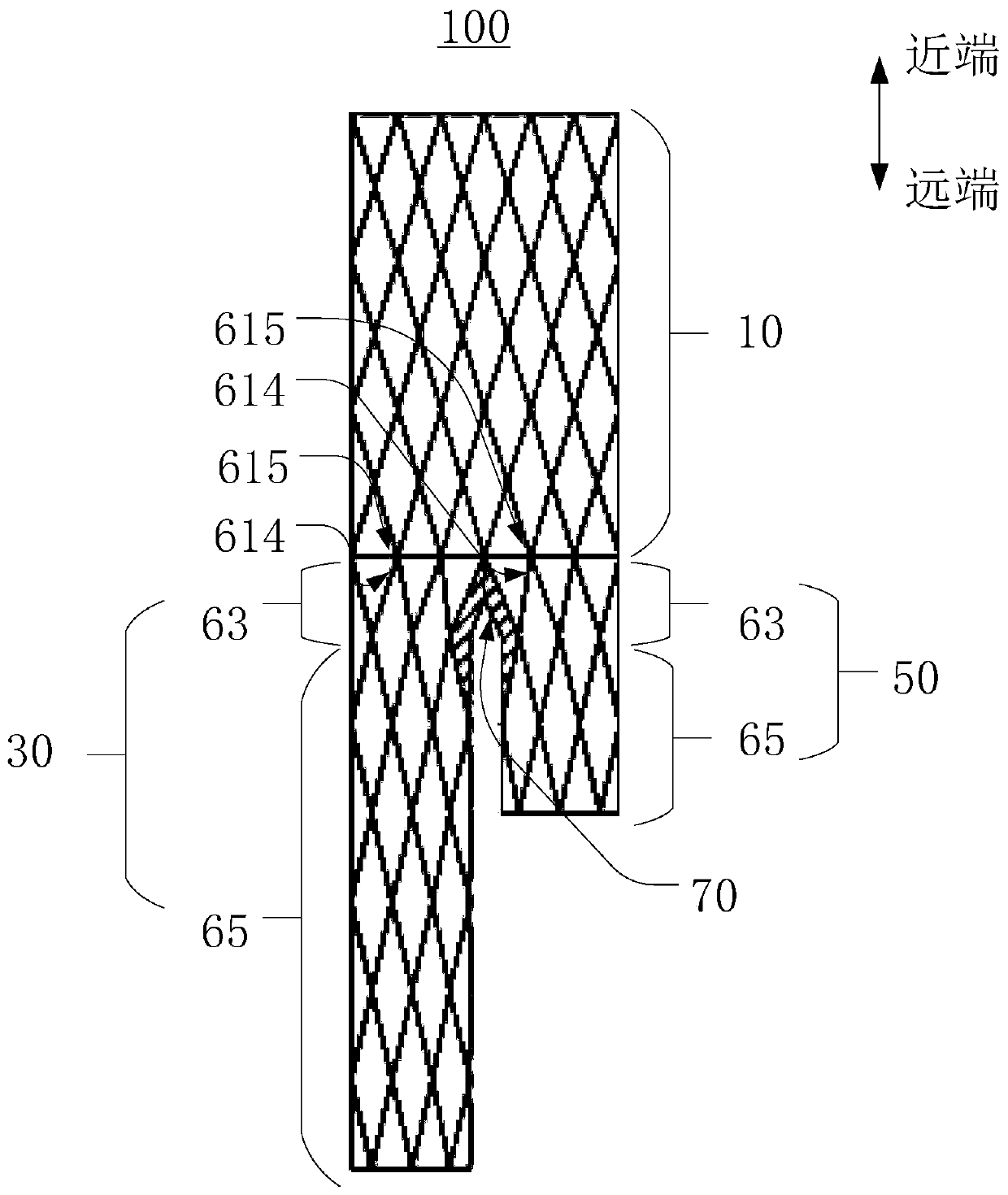
[0030] see figure 1 , figure 1 It is a schematic structural diagram of the bifurcated stent provided in the first embodiment of the present application.

[0031] The present application discloses a bifurcated stent 100, which includes a main body 10, a first branch 30 and a second branch 50, the first branch 30 and the second branch 50 are connected to the same end of the main body 10, the main body 10, the first branch 30 and the second branch 50 are all mesh structures, and the bifurcated stent 100 also includes a bifurcated region 70 connected between the first branch 30 and the second branch 50, in figure 1 In order to facilitate understanding, the bifurcation region 70 is represented by parallel oblique lines that are denser than other regions, but these oblique lines are only used to indicate the location of the region, and are not used to limit the specific structural form in the bifurcation region 70, such as bifurcation The braiding method of the braided wire in the...

no. 2 approach

[0066] Please also refer to Figure 12 and Figure 13 , Figure 12 It is a schematic structural diagram of the bifurcated stent provided in the second embodiment of the present application, Figure 13 for Figure 12 Schematic diagram of the structure of the bifurcated stent shown looking up.

[0067] Compared with the bifurcated bracket 100 provided in the first embodiment, the bifurcated bracket 300 provided in this embodiment is mainly different in that: the bifurcated bracket 300 provided in this embodiment also includes a connecting piece 390 connected to the first branch 330 and the network structure of the second branch 350 , the grid density of the bifurcated stent 300 in the bifurcated area 370 is greater than that of other areas of the bifurcated stent 300 .

[0068] It can be understood that the connecting member 390 is not limited to be connected between the network structure of the first branch 330 and the second branch 350, for example, the connecting member 3...

no. 3 approach

[0073] Please refer to Figure 14 and Figure 15 , Figure 14 Schematic view of the structure of the bifurcation support provided in the third embodiment of the present application; Figure 15 for Figure 14 A partially enlarged schematic of the bifurcated scaffold is shown.

[0074] Compared with the bifurcated stent 300 provided in the second embodiment, the bifurcated stent 400 provided in this embodiment is mainly different in that: the connecting piece 490 of the bifurcated stent 400 is a coiled wire, and the coiled wire is used to connect to the first branch 430 and between the network structure of the second branch 450 . Specifically, the winding wire is fixedly connected between the two wave rods 4612 located in the first branch 430 and the second branch 450 .

[0075] It can be understood that the number of winding wires is not limited. For example, the number of wrapping wires can be but not limited to be multiple. It can be understood that, when there are mul...


PUM


Abstract

The application discloses a bifurcation bracket. The bifurcation bracket comprises a main body, a first branch and the second branch. The first branch and the second branch are both connected to the same end of the main body. The main body, the first branch and the second branch are all mesh structures. The bifurcation bracket further includes a bifurcation area connected between the first branchand the second branch. The grid density of the bifurcation bracket in the bifurcation region is greater than the grid density in other regions of the bifurcation bracket. In this way, the contact areabetween the bifurcation area of the bifurcation bracket and the blood vessel wall at the bifurcation position is increased, and the bifurcation area can support the blood vessel wall at the bifurcation position. In addition, since the grid density of the bifurcation region is greater than that of other regions of the bifurcation bracket, embolism caused by the shedding of mural thrombus at the bifurcation position can be prevented.

Description

technical field [0001] The present application relates to implantable devices for use in a patient, and in particular to a bifurcated stent. Background technique [0002] With the improvement of people's living standards and changes in lifestyle, the incidence of vascular diseases is increasing. If these diseases are not treated in time, they may lead to blood vessel blockage, aneurysm and other diseases, which will seriously endanger human life. [0003] At present, minimally invasive interventional surgery can be used to treat vascular diseases. Such methods cause less trauma to patients, are highly safe, and have high effectiveness. Therefore, they are affirmed by operators and patients and have become an important treatment method for vascular diseases. Interventional treatment refers to the use of a delivery system to implant a stent into the diseased segment of the patient's blood vessel. The implanted stent can support the stenotic occluded segment of the blood vessel...

Claims


Application Information

Patent Timeline
Patent Type & Authority Applications(China)
IPC IPC(8): A61F2/86
CPCA61F2/86
Inventor 董智慧符伟国刘浩李安伟任博翰王永胜
Owner HANGZHOU WEIQIANG MEDICAL TECH CO LTD
Why Eureka
Try Eureka