Liquid-liquid two-phase separation system for unsteady state feeding partial emulsification and application

A non-steady state, phase separation technology, applied in the field of chemical production, can solve the problems of the centrifuge system not running normally, not having industrial application value, extremely unstable feeding state, etc., to improve the completeness of separation and the economic benefits of operation. Significant, small footprint effect

Pending Publication Date: 2020-07-24
ZHEJIANG ZHONGLI SYNTHETIC MATERIAL TECH CO LTD
View PDF0 Cites 0 Cited by
  • Summary
  • Abstract
  • Description
  • Claims
  • Application Information

AI Technical Summary

Problems solved by technology

Due to the existence of a small amount of polymer, refining treatment cannot be used; natural sedimentation requires a large site and settling time, and has no industrial application value; direct centrifugal treatment, the intensification of emulsification and the extreme instability of the feed state make the centrifuge system completely not functioning properly
The production of the whole set of equipment was seriously hindered due to the problem of separation

Method used


Image

  • Liquid-liquid two-phase separation system for unsteady state feeding partial emulsification and application
  • Liquid-liquid two-phase separation system for unsteady state feeding partial emulsification and application
  • Liquid-liquid two-phase separation system for unsteady state feeding partial emulsification and application

Examples


Embodiment 1

[0036] Deep separation of light components with variable working conditions

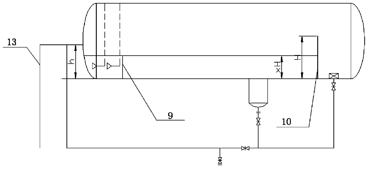
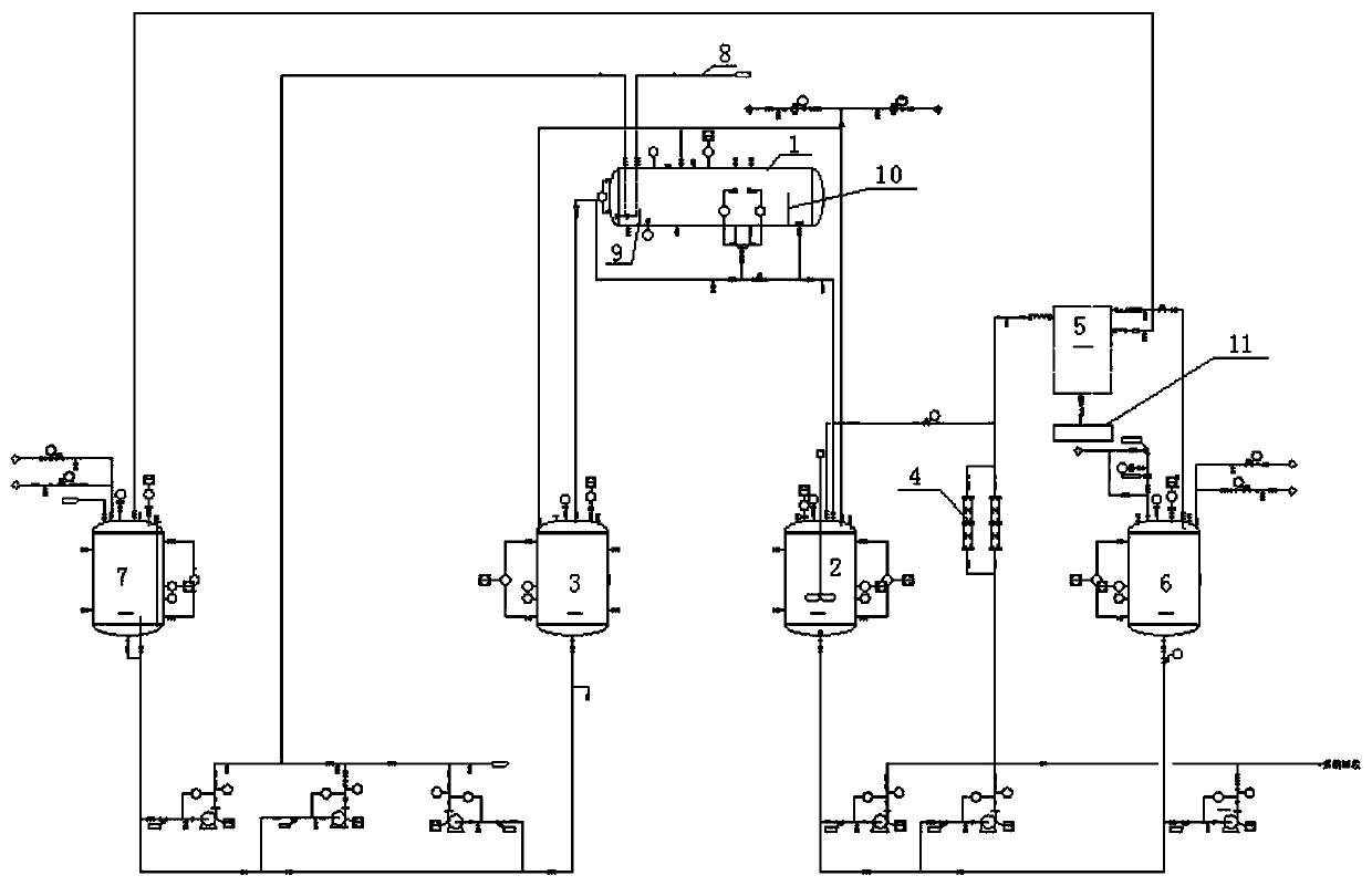
[0037] refer to figure 1 , figure 2 , Figure 5 , a liquid-liquid two-phase separation system with partial emulsification of unsteady feed, the system includes a pre-separation tank 1, a light component collection tank 2, a heavy component collection tank 3, an extrusion demulsification device 4, a centrifuge 5 and a recovery tank 6, the pre-separation tank 1 is a horizontal tank structure, the light component collection tank 2 and the heavy component collection tank 3 are vertical tank structures, and the centrifuge is a three-phase centrifuge. The three-phase centrifuge 5 is communicated with the circulation tank 7, and the circulation tank 7 is communicated with the pre-separation tank 1; the pre-separation tank 1 is communicated with the separation liquid inlet pipe 8, and the separation liquid inlet pipe 8, The circulation tank 7 extends into the bottom of the pre-separation tank through the...

Embodiment 2

[0047] Implementation of regrouping and deep separation with changing working conditions

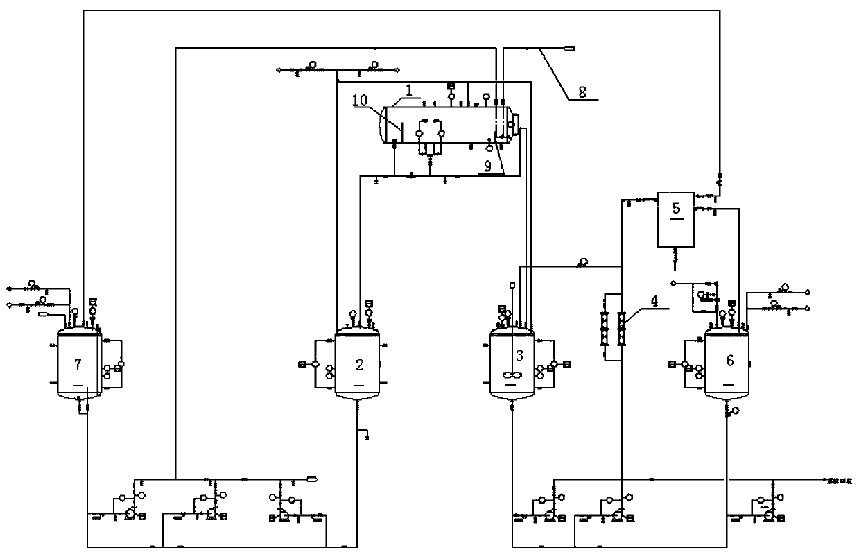
[0048] refer to figure 1 , image 3 , Figure 5 Referring to Example 1 for other structures of a partially emulsified liquid-liquid two-phase separation system with unsteady feed, the pre-separation tank 1 is connected to the light component collection tank 2 and the heavy component collection tank 3 respectively, so The light component collecting tank 2 is not provided with a stirring device, and the heavy component collecting tank 3 is provided with a stirring device; The three-phase centrifuge 5 is connected, and the three-phase centrifuge 5 is connected with the recovery tank 6; the light component collection tank 2 is connected with the circulation tank 7; the light and heavy component collection tank 3 and the recovery tank 6 are respectively connected with The system recovery device is connected; the three-phase centrifuge 5 is connected to the centrifuge slag tank 11 . The to...

Embodiment 3

[0054] Implementation of deep separation of light and heavy components under changing working conditions

[0055] refer to figure 1 , Figure 4 , Figure 5 , a kind of non-steady-state feed partial emulsified liquid-liquid two-phase separation system with reference to embodiment 1, the collection tank includes a light component collection tank 2 and a heavy component collection tank 3, the light component collection tank The tank 2 and the heavy component collection tank 3 are all equipped with agitators; the pre-separation tank 1 communicates with the light component collection tank 2 and the heavy component collection tank 3 respectively, and the light component collection tank 2 is connected to the first extrusion The demulsification device 4-1 is connected, the first demulsification device 4-1 is connected with the first centrifuge 5-1, and the first centrifuge 5-1 is connected with the first recovery tank 6-1 The heavy component collection tank 3 is communicated with t...


PUM

PropertyMeasurementUnit
Heightaaaaaaaaaa

Abstract

The invention relates to a liquid-liquid two-phase separation system for unsteady state feeding partial emulsification and application. The liquid-liquid two-phase separation system comprises a pre-separation tank, a collection tank, an extrusion demulsification device, a centrifuge and a recovery tank, the centrifuge is also communicated with a circulation tank, and the circulation tank is communicated with the pre-separation tank; the pre-separation tank is communicated with a separation liquid inlet pipe, and the separation liquid inlet pipe and the circulation tank respectively extend intothe bottom of the pre-separation tank through corresponding insertion pipes; a first baffle and a second baffle are arranged in the pre-separation tank, the first baffle is close to the insertion pipe, and the second baffle is close to one side of a heavy component assembly bag; and the pre-separation tank is communicated with a heavy component collection tank through a siphon. According to the invention, the production efficiency can be greatly improved, the separation thoroughness is improved, and the equipment size is reduced; meanwhile, only the separation degree of an outlet in one sideof the centrifugal machine needs to be improved to guarantee the separation precision, the operation condition of the other side does not need to be considered, the system operation stability and thefeeding adaptive capacity are greatly improved, and the working condition of large-range fluctuation can be met.

Description

technical field [0001] The invention belongs to the technical field of chemical production, and in particular relates to a liquid-liquid two-phase separation system for partial emulsification of unsteady feed and its application. Background technique [0002] Separation of two-phase and multi-phase liquid-phase mixtures is an essential processing skill in modern chemical production processes. For liquid phase mixing that requires a high degree of separation, modern chemical industry mostly adopts rectification for separation and purification. The notable feature is the high precision of the separated products, but the energy consumption is high, and the primary investment involved in the automatic control system is large. For the application fields that do not require high separation accuracy, especially the separation of the mixing system with low self-compatibility of the liquid phase, the density difference under the action of the gravity field is more often used for stat...

Claims


Application Information

Patent Timeline
IPC IPC(8): B01D17/038B01D17/04C02F1/40C02F1/38C02F9/04
CPCB01D17/0217B01D17/04B01D17/047C02F1/40C02F1/38Y02W30/62
Inventor 文强叶挺朱国涛谢叶波
Owner ZHEJIANG ZHONGLI SYNTHETIC MATERIAL TECH CO LTD
Why Eureka
Try Eureka