Lightweight four-degree-of-freedom leg mechanism of four-foot bionic robot

A technology of bionic robot and leg mechanism, which is applied in manipulators, motor vehicles, program-controlled manipulators, etc. It can solve the problems of poor dynamic response speed, limited motion accuracy and response speed, long connecting pipelines, etc., and achieve action response Fast, easy and precise measurement, strong load resistance effect

Active Publication Date: 2020-07-24
YANSHAN UNIV
View PDF10 Cites 13 Cited by
  • Summary
  • Abstract
  • Description
  • Claims
  • Application Information

AI Technical Summary

Problems solved by technology

[0003] At present, the leg mechanism of the hydraulic quadruped robot mainly adopts the hydraulic drive of the external pipeline, and the arrangement of the leg mechanism is relatively scattered. The following disadvantages exist for this kind of leg structure: 1. The joint mass is large, the range of motion is small, and the driving ability is insufficient , Motion accuracy and response speed are limited; 2. The connecting pipeline between the servo valve and the servo cylinder is too long, which reduces the natural frequency of the system, resulting in poor dynamic response speed and increased hydraulic power loss, which restricts the walking of the hydraulic quadruped robot Capabilities and Engineering Utilization
[0005] To sum up, hydraulic quadruped bionic robots have broad prospects for development, but at present, the integration of their leg structures is not high enough, their flexibility and response speed are poor, their joint mass is large, their driving ability is insufficient, and their hydraulic power loss is large. Meet the high-performance needs of hydraulic quadruped bionic robots for high-end mobile equipment

Method used


Image

  • Lightweight four-degree-of-freedom leg mechanism of four-foot bionic robot
  • Lightweight four-degree-of-freedom leg mechanism of four-foot bionic robot
  • Lightweight four-degree-of-freedom leg mechanism of four-foot bionic robot

Examples


Embodiment Construction

[0031] The following will clearly and completely describe the technical solutions in the embodiments of the present invention with reference to the accompanying drawings in the embodiments of the present invention. Obviously, the described embodiments are only some, not all, embodiments of the present invention. Based on the embodiments of the present invention, all other embodiments obtained by persons of ordinary skill in the art without making creative efforts belong to the protection scope of the present invention.

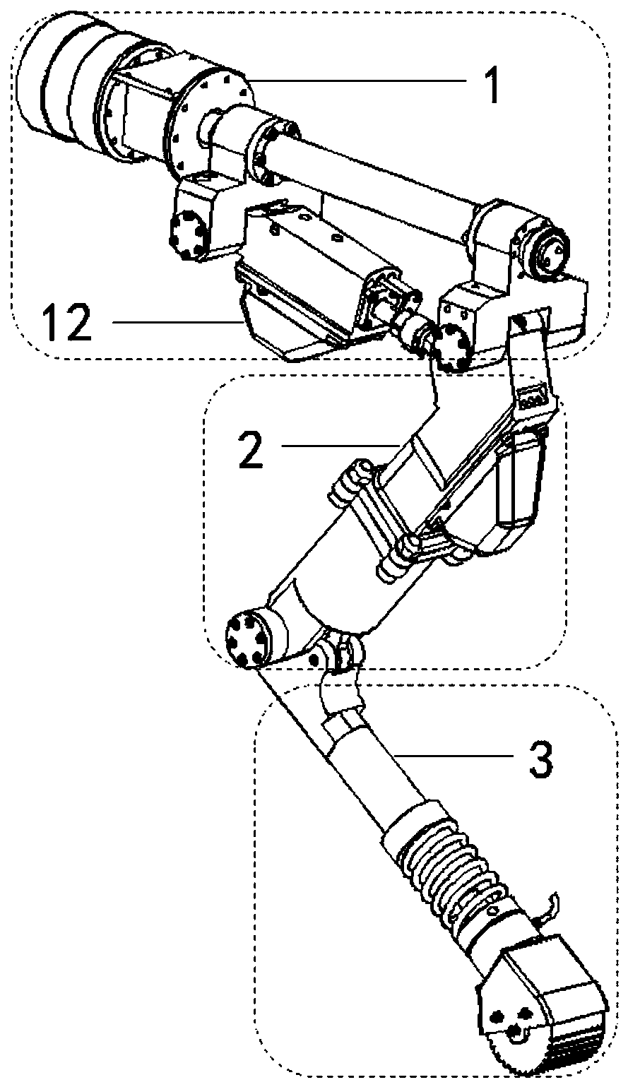
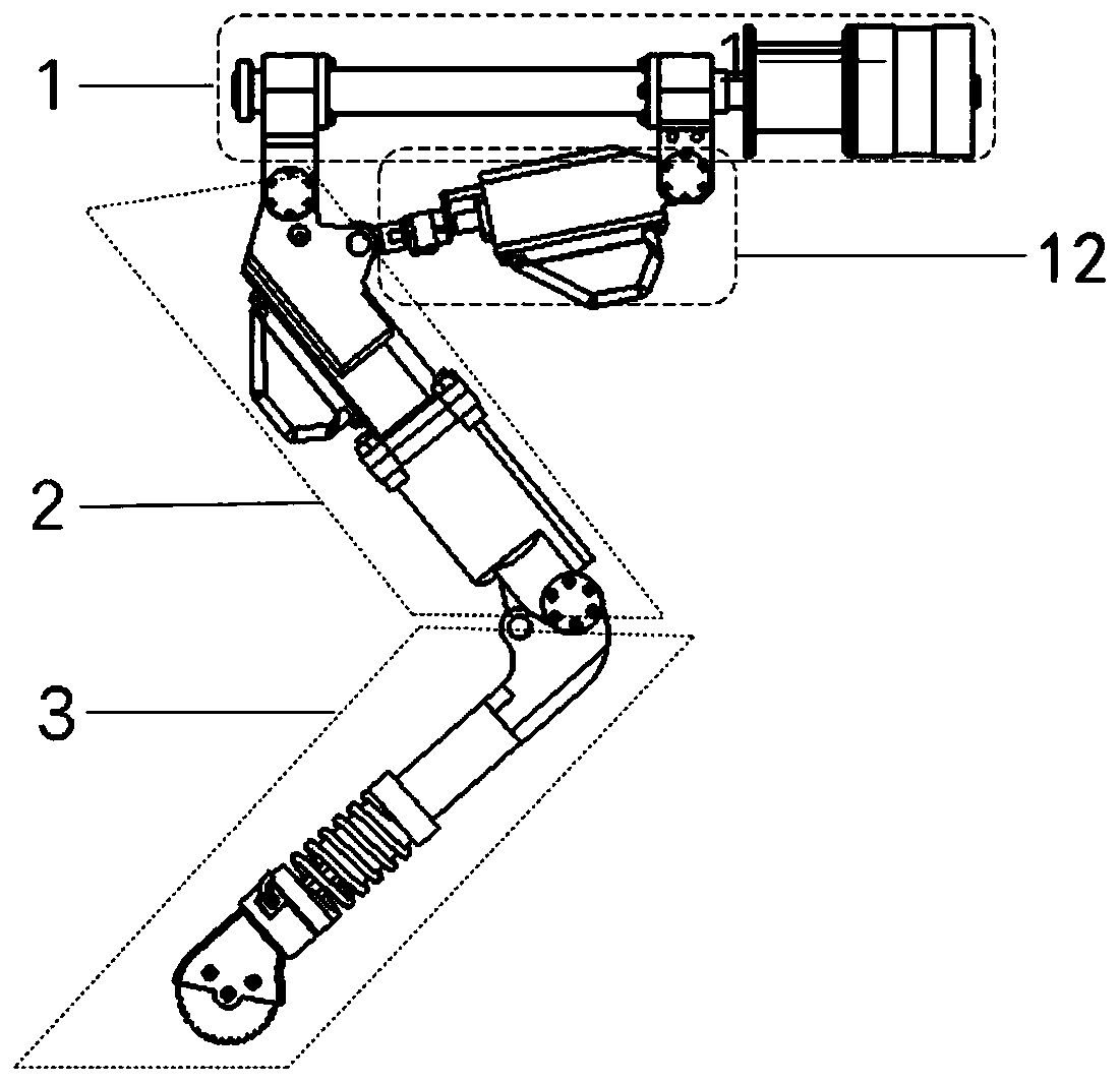
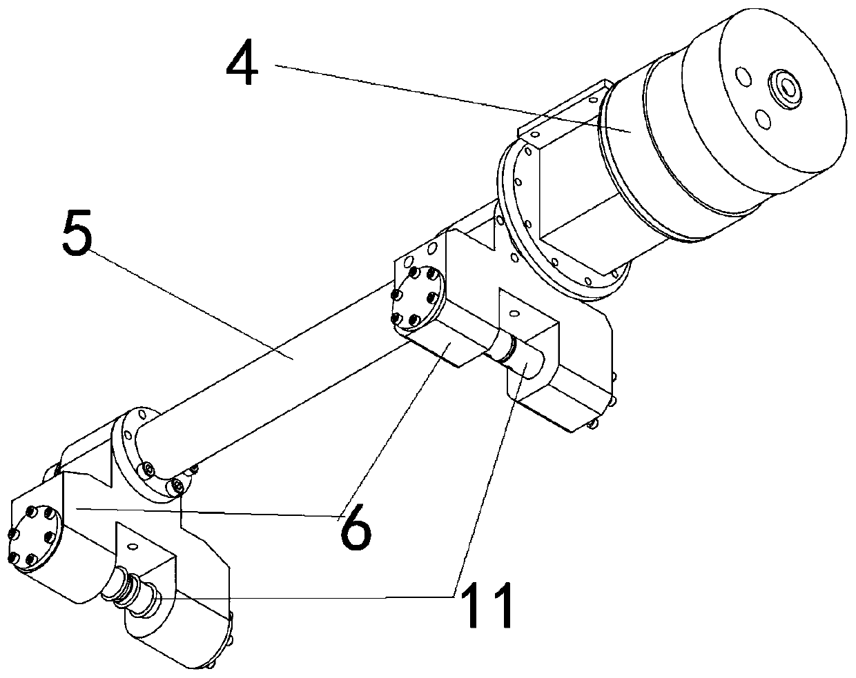
[0032] The purpose of the present invention is to provide a light-weight four-degree-of-freedom leg mechanism of a quadruped bionic robot to solve the problems existing in the prior art, so that the leg mechanism can achieve highly integrated lightweight without external hydraulic pipelines, and the legs can be lifted Institutional flexibility.

[0033] In order to make the above objects, features and advantages of the present invention more comprehensible, th...


PUM


Abstract

The invention discloses a lightweight four-degree-of-freedom leg mechanism of a four-foot bionic robot. The leg mechanism comprises a hip joint yawing assembly, a thigh yawing assembly and a shank yawing assembly, the hip joint yawing assembly comprises a hip joint swing cylinder and an electro-hydraulic actuator, one end of the electro-hydraulic actuator and one end of the thigh yawing assembly are hinged to the hip joint swing cylinder through connecting blocks respectively, the other end of the electro-hydraulic actuator is hinged to the side face of the thigh yawing assembly, and the otherend of the thigh yawing assembly is hinged to the shank yawing assembly. According to the four-degree-of-freedom leg mechanism of the four-foot bionic robot, through the integrated oil way design, light weight is achieved, the hip joint swing cylinder is driven and controlled by the hydraulic pump, the load resistance is high, the power-to-weight ratio is high, the electro-hydraulic actuator andthigh longitudinal swing general assembly is quick in action response, kinetic parameters are easy to accurately measure, and four-degree-of-freedom motion with three active degrees of freedom and onepassive degree of freedom can be achieved.

Description

technical field [0001] The invention relates to the technical field of bionic robot components, in particular to a lightweight four-degree-of-freedom leg mechanism of a quadruped bionic robot. Background technique [0002] With the rapid development of science and technology in the 21st century, high-end mobile equipment such as construction machinery, metallurgical machinery, aircraft, power-assisted exoskeletons, and quadruped bionic robots have been extensively researched and applied. There are two main types of motion for high-end mobile equipment: wheel motion and foot motion. Foot movements are favored due to their ability to adapt well to unstructured environments and their high flexibility in the legs. The legged bionic robots can be divided into two-legged, four-legged, six-legged and multi-legged. Among them, quadruped bionic robots have the widest application range and the highest practicability in the fields of disaster relief, daily handling, entertainment and ...

Claims


Application Information

Patent Timeline
Patent Type & Authority Applications(China)
IPC IPC(8): B62D57/032
CPCB62D57/032B25J9/144B25J13/085B25J19/0091B25J17/0258
Inventor 俞滨巴凯先杨建奎朱琦歆黄智鹏袁立鹏
Owner YANSHAN UNIV
Why Eureka
Try Eureka