Ultrasonic friction stir welding composite welding system

A hybrid welding and ultrasonic stirring technology, which is used in welding equipment, non-electric welding equipment, metal processing equipment, etc., can solve the problems of small ultrasonic amplitude, inability to obtain high-quality welds, and low ultrasonic energy density.

Active Publication Date: 2021-05-18
DALIAN JIAOTONG UNIVERSITY
View PDF11 Cites 2 Cited by
  • Summary
  • Abstract
  • Description
  • Claims
  • Application Information

AI Technical Summary

Problems solved by technology

The above patents all use a single ultrasonic transducer to provide ultrasonic energy, which is amplified by a first-stage ultrasonic horn. This design can obtain a higher ultrasonic energy when the welding device is running freely, but under heavy load conditions , the actual effective ultrasonic amplitude in the welding area is small, the output ultrasonic energy density is low, and high-quality welds cannot be obtained

Method used


Image

  • Ultrasonic friction stir welding composite welding system
  • Ultrasonic friction stir welding composite welding system
  • Ultrasonic friction stir welding composite welding system

Examples


Embodiment 1

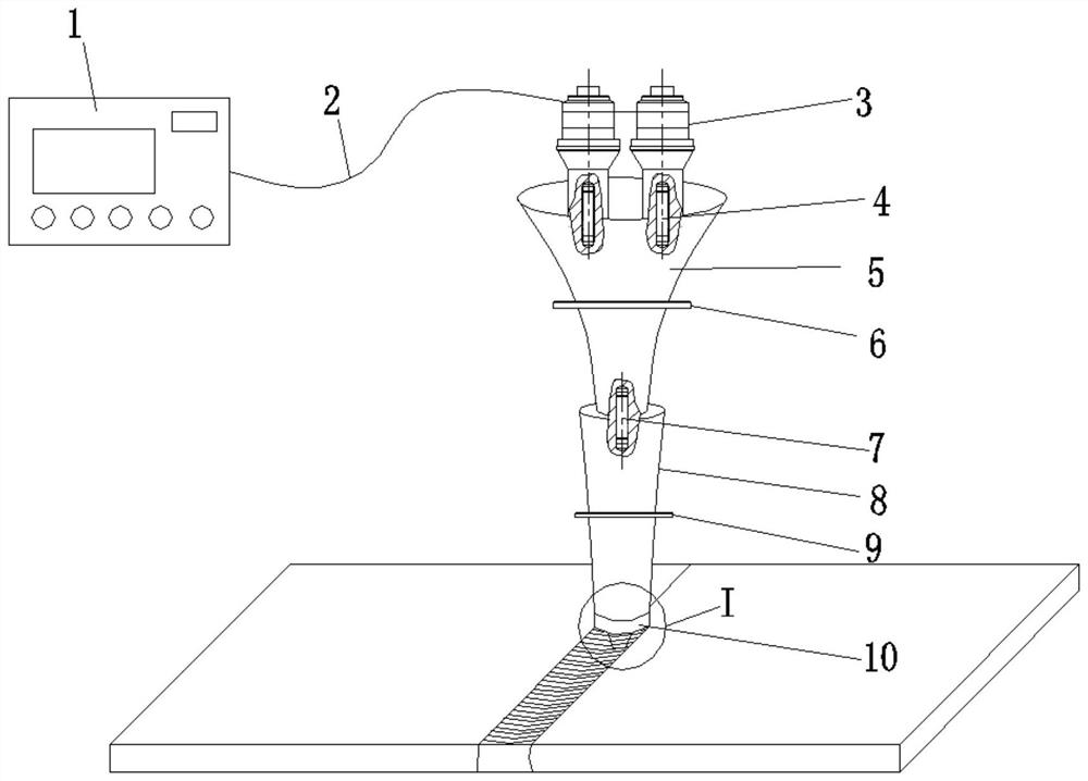
[0049] Such as Figure 1~2 As shown, an ultrasonic friction stir welding hybrid welding system includes:

[0050] A pre-stage ultrasonic horn 5, the front end of the pre-stage ultrasonic horn 5 fixes two ultrasonic transducers 3 through stud bolts I4; the ultrasonic transducer 3 is connected to the power supply 1 through a wire 2;

[0051] A rear-stage ultrasonic horn 8, the front end of which is tightly fixedly connected to the rear ends of all the preceding ultrasonic horns 5 through stud bolts II7;

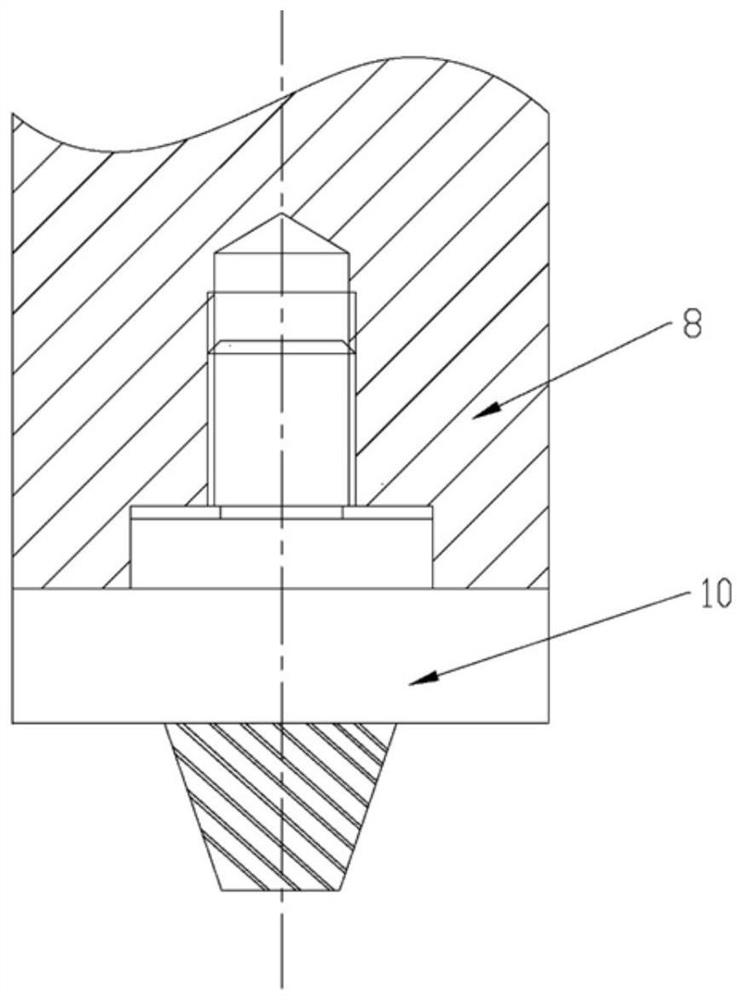
[0052] The stirring head 10 is fixedly connected to the rear end of the rear-stage ultrasonic horn 8; the circular end face of the stirring head 10 is closely connected with the end face of the rear-stage ultrasonic horn 8, and the front end of the stirring head 10 The cylindrical section enters the shaft hole at the rear end of the rear-stage ultrasonic horn 8 to achieve radial positioning and is fixedly connected by bolts.

[0053] Flange I6 and flange II9 are respectively ...

Embodiment 2

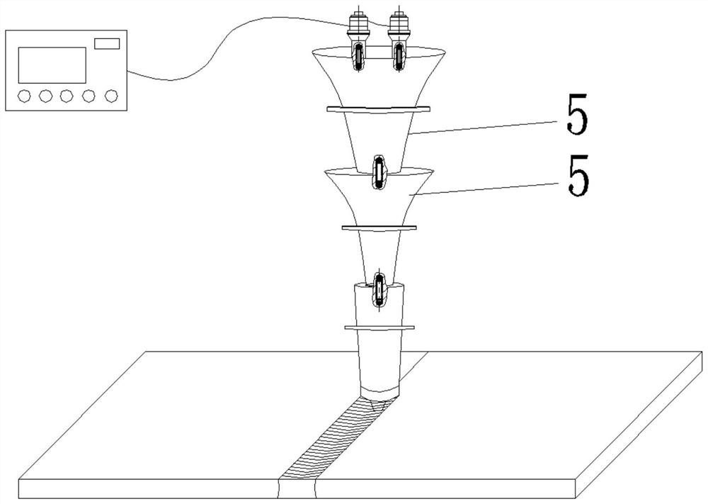
[0070] Such as image 3 As shown, an ultrasonic friction stir welding composite welding system, the difference between this embodiment and Embodiment 1 is that there are two front-stage ultrasonic horns 5 connected in series in this embodiment, and the front-end ultrasonic horn 5 is located at the front end The front end of the front-stage ultrasonic horn 5 is fixedly connected to the ultrasonic transducer 3, and the rear end of the front-stage ultrasonic horn 5 positioned at the rear end is fixedly connected to the front end of the rear-stage ultrasonic horn 8 .


PUM


Abstract

The invention provides an ultrasonic friction stir welding composite welding system. The system is characterized in that the ultrasonic friction stir welding composite welding system comprises at least one front-stage ultrasonic amplitude-change pole, a rear-stage ultrasonic amplitude-change pole and a stirring head, and at least one ultrasonic transducer is fixed to the front end of each front-stage ultrasonic amplitude-change pole; the front end of the rear-stage ultrasonic amplitude-change pole is fixedly connected with the rear ends of all the front-stage ultrasonic amplitude-change poles; the stirring head is fixedly connected with the rear end of the rear-stage ultrasonic amplitude-change pole; the front-stage ultrasonic amplitude-change poles are high-order polynomial type half-wavelength ultrasonic amplitude-change poles, and the amplification factor of the front-stage ultrasonic amplitude-change poles is a large amplification factor; and the rear-stage ultrasonic amplitude-change pole is a half-wavelength ultrasonic amplitude-change pole, and the amplification factor of the rear-stage ultrasonic amplitude-change pole is a small amplification factor. According to the system, a high-power multi-vibrator ultrasonic vibration system is used for increasing the driving power of the system, improving the ultrasonic energy density in the welding process and improving the welding efficiency, and the high-power ultrasonic vibration system achieves the effects of increasing the ultrasonic amplitude and enhancing the anti-load capacity of the system by designing a multi-stage amplitude-change pole.

Description

technical field [0001] The invention relates to the technical field of friction stir welding, in particular to an ultrasonic friction stir composite welding system that can effectively increase the amplitude and improve the load resistance capability, and in particular to an ultrasonic friction stir welding composite welding system. Background technique [0002] In order to solve the problems such as traditional inert gas shielded welding and other fusion welding that are prone to produce pores, thermal cracks, and joint softening, the British Welding Institute invented a new solid-phase joining technology in 1991 - friction stir welding. Friction stir welding uses the friction heat generated between the rotating stirring head and the workpiece to be welded to heat the aluminum alloy to a plastic state, and realizes welding through the plastic flow of the material. Due to the low welding temperature, it overcomes the shortcomings of TIG and MIG welding , providing a new weld...

Claims


Application Information

Patent Timeline
Patent Type & Authority Applications(China)
IPC IPC(8): B23K28/02B23K20/10B23K20/12
CPCB23K28/02B23K20/10B23K20/122
Inventor 马付建宋浩焦首岳杨大鹏刘宇沙智华张生芳
Owner DALIAN JIAOTONG UNIVERSITY
Why Eureka
Try Eureka