Multifunctional steam trap

A steam trap, multi-functional technology, applied in steam traps, valve details, valve devices, etc., can solve the problem of single function of steam traps, achieve good steam-water separation performance, strong adaptability, and improve heat exchange efficiency

Pending Publication Date: 2020-07-24
于淼
View PDF0 Cites 3 Cited by
  • Summary
  • Abstract
  • Description
  • Claims
  • Application Information

AI Technical Summary

Problems solved by technology

[0004] The purpose of the present invention is to provide a multifunctional steam trap to solve the technical problem of the single function of the trap in the prior art

Method used


Image

  • Multifunctional steam trap
  • Multifunctional steam trap
  • Multifunctional steam trap

Examples


Embodiment Construction

[0041] In order to make the purpose, technical solution and advantages of the present invention clearer, the technical solution of the present invention will be described in detail below. Apparently, the described embodiments are only some of the embodiments of the present invention, but not all of them. Based on the embodiments of the present invention, all other implementations obtained by persons of ordinary skill in the art without making creative efforts fall within the protection scope of the present invention.

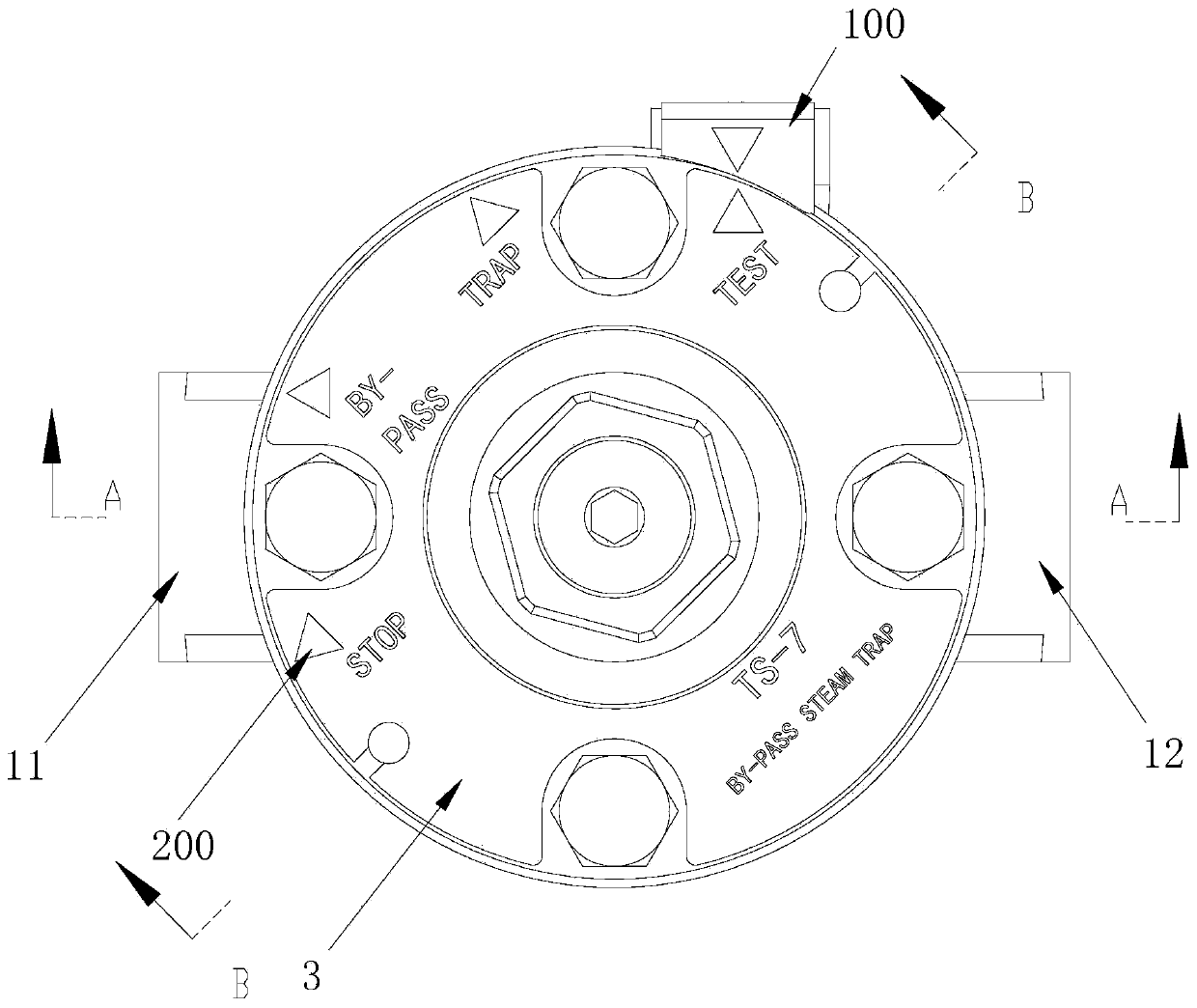
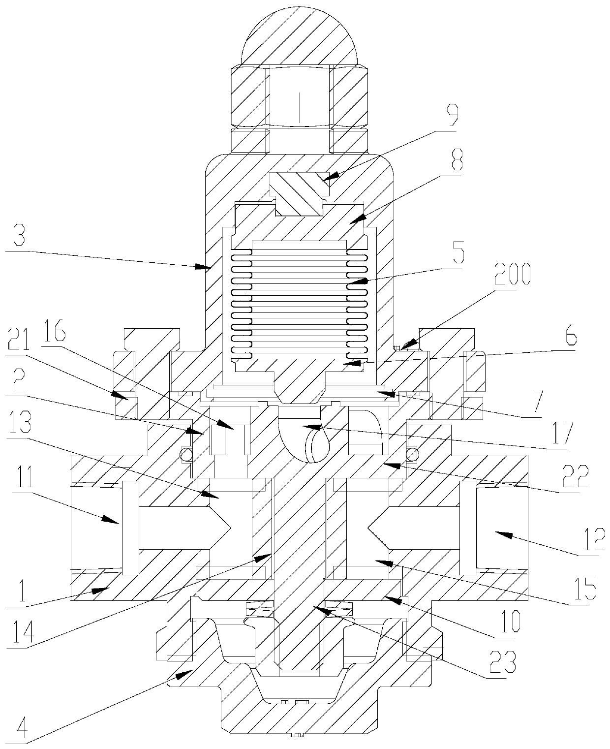
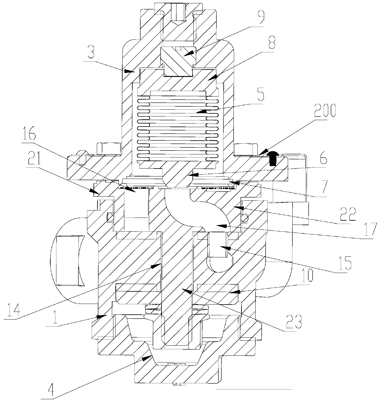
[0042] Such as figure 2 with image 3 As shown, the present invention provides a multifunctional steam trap, which includes a valve body 1, a valve seat 2, a function switching assembly, a valve cover 3, a bottom end cover 4, a hydrophobic function module 5 and a valve core 6, and on the valve body 1 An inlet 11 and an outlet 12 are provided, and a plurality of fluid passages communicating with the inlet 11 and the outlet 12 are arranged inside, the valve sea...


PUM


Abstract

The invention provides a multifunctional steam trap which comprises a valve body, a valve seat, a function switching assembly, a valve deck, a bottom end cover, a drainage function module and a valveelement. An inlet and an outlet are formed in the valve body, a plurality of fluid channels communicated with the inlet and the outlet are formed in the valve body, the valve seat movably penetrates through the top of the valve body, and the valve deck covers the top of the valve seat; one end of the hydrophobic function module abuts against the valve deck, the other end of the hydrophobic function module is connected with the valve element, and the valve element can be driven to move to abut against the valve seat or be separated from the valve seat; the bottom end cover is arranged at the bottom of the valve body, and the function switching assembly is arranged on the valve seat and stretches across each fluid channel; and when the valve seat moves, the function switching assembly can bedriven to move to enable any one fluid channel to be in a connected state or all the fluid channels to be in a cut-off state, so that the multifunctional steam trap valve is controlled to be switchedin different function modes. According to the multifunctional steam trap, a plurality of functional modes can be manually switched, the functions of cut-off, drainage and conduction are achieved, anddifferent functional modes can be selected and used according to actual needs.

Description

technical field [0001] The invention relates to the technical field of fluid equipment, in particular to a heat pipe type temperature-variable multifunctional steam trap. Background technique [0002] The function of the steam trap is to automatically remove the condensed water, air and non-condensable gas that are continuously generated in the steam heating equipment or steam pipe network. At the same time, it prevents the steam from being discharged with the water, so the steam trap is also called the steam-resistance drain valve. [0003] At present, the commonly used thermostatic steam traps and thermodynamic steam traps can only play the function of draining water, but have no other functions. They have a single function and a narrow scope of application. Contents of the invention [0004] The purpose of the present invention is to provide a multifunctional steam trap to solve the technical problem of the single function of the trap in the prior art. [0005] To ach...

Claims


Application Information

Patent Timeline
Patent Type & Authority Applications(China)
IPC IPC(8): F16T1/06F16T1/38F16K13/00F16K27/02F16K27/04F16K31/64F16K37/00
CPCF16K13/00F16K27/02F16K27/045F16K31/002F16K37/0008F16T1/06F16T1/383F16T1/386
Inventor 于淼
Owner 于淼
Why Eureka
Try Eureka