
Optical sensing device

A technology of optical sensing and optical structure, which is applied in the field of semiconductors, can solve problems such as full value and sensing of object distance affecting the photosensitive element 102, and achieve the effects of reducing size, reducing process cost, and reducing optical crosstalk

Pending Publication Date: 2020-07-24
SILERGY SEMICON TECH (HANGZHOU) CO LTD
View PDF0 Cites 5 Cited by
  • Summary
  • Abstract
  • Description
  • Claims
  • Application Information

AI Technical Summary

Problems solved by technology

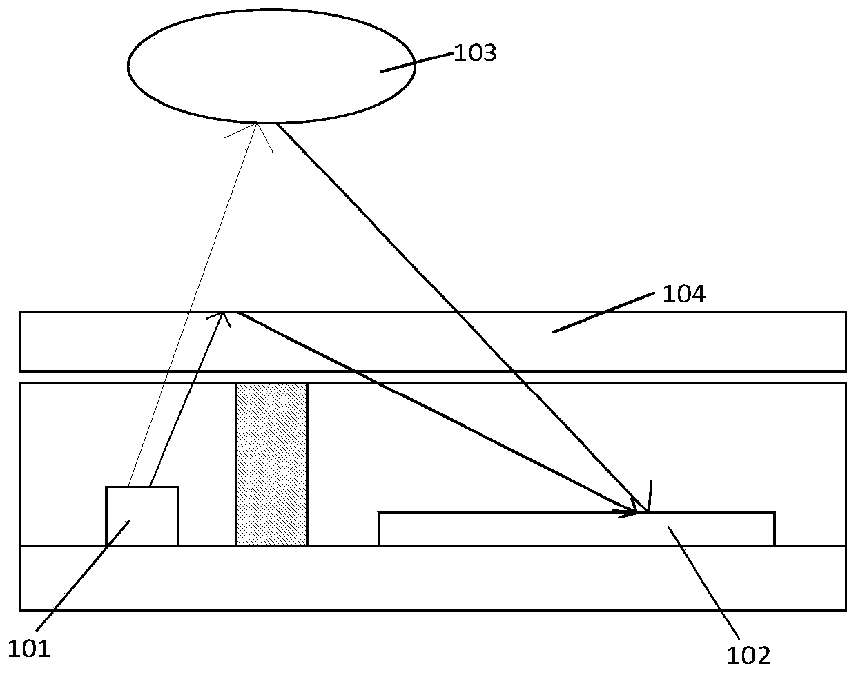
However, the photosensitive element 102 will also receive light reflected from the cover plate 104 at the same time. This kind of reflected light is generally a large-angle reflected light, which directly affects the sensing of the object distance by the photosensitive element 102.
In addition, the light energy received by the Proximity sensor in the prior art is inversely proportional to the square of the distance from the detected object. When the object is very close to the Proximity sensor, the phenomenon of full count (full count) is prone to occur.

Method used


Image

  • Optical sensing device
  • Optical sensing device
  • Optical sensing device

Examples


Embodiment Construction

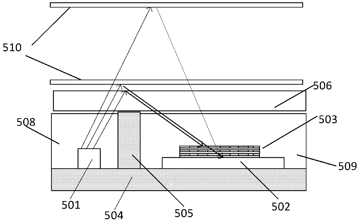
[0037] Hereinafter, the present invention will be described in more detail with reference to the accompanying drawings. In the various figures, identical elements are indicated with similar reference numerals. For the sake of clarity, various parts in the drawings have not been drawn to scale. Also, some well-known parts may not be shown. For the sake of simplicity, the semiconductor structure obtained after several steps can be described in one figure.

[0038] It should be understood that when describing the structure of a device, when a layer or a region is referred to as being "on" or "over" another layer or another region, it may mean being directly on another layer or another region, or Other layers or regions are also included between it and another layer or another region. And, if the device is turned over, the layer, one region, will be "below" or "beneath" the other layer, another region.

[0039] If it is to describe the situation directly on another layer or an...


PUM

PropertyMeasurementUnit
thicknessaaaaaaaaaa
thicknessaaaaaaaaaa

Abstract

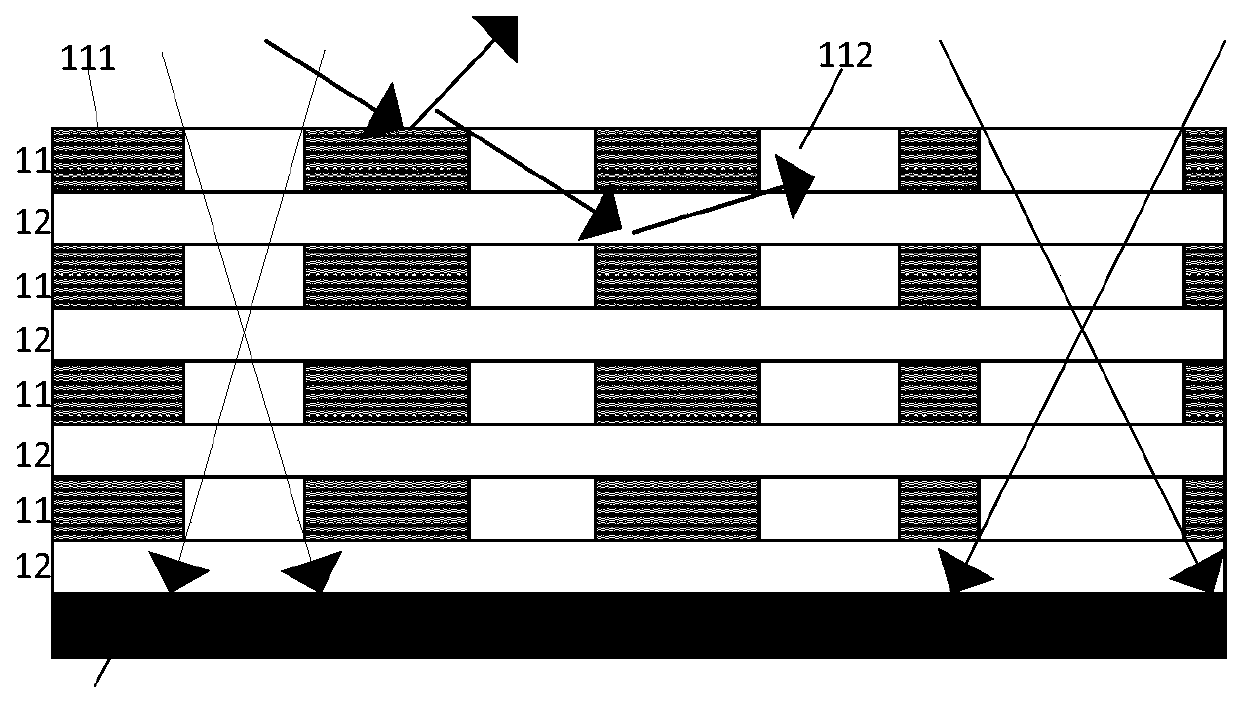
The invention provides an optical sensing device. The device comprises at least one semiconductor with a photosensitive area and an optical structure. The optical structure is positioned above the photosensitive area; and the optical structure comprises a light filtering layer and a light transmitting layer which are alternately stacked so as to prevent large-angle incident light from entering thephotosensitive area and reduce optical crosstalk.

Description

technical field [0001] The present invention relates to the technical field of semiconductors, and more particularly, to an optical sensing device. Background technique [0002] The main principle of the proximity sensor (Proximity Sensor) application is to emit light from a reference light source. After the light is reflected by an object, it is received by a photodiode (Photo Diode, PD), and the light energy is converted into an electrical signal. The distance between the object and the package is determined by the strength of the electrical signal (light energy). The signal strength is strong when the object is near, and the signal strength is weak when the object is far away. [0003] In practical applications, the light energy received by the PD includes not only the reflection from the detection object, but also the reflection from other non-detection objects. The light that does not belong to the reflection of the detection object is called crosstalk (Cross-talk). To...

Claims


Application Information

Patent Timeline
Patent Type & Authority Applications(China)
IPC IPC(8): H01L31/0232
CPCH01L31/02327H01L31/167H01L31/02162H01L31/0203H01L31/02325G01S17/04G01S7/4816G01S7/4813G01S17/08H01L31/02024H01L31/125
Inventor 钟炜竣林苏逸
Owner SILERGY SEMICON TECH (HANGZHOU) CO LTD
Learn More