Wire connection device and using method thereof

A splicing device and wire joint technology, which is applied in the direction of conductive connection, connection, and electrical component connection, can solve the problems of unfavorable fast operation, easy wear of wires, and slow connection speed, so as to improve connection efficiency, avoid torsion fracture, and weaken the effect force effect

Pending Publication Date: 2020-07-24
国网河南省电力公司宝丰县供电公司
View PDF0 Cites 2 Cited by
  • Summary
  • Abstract
  • Description
  • Claims
  • Application Information

AI Technical Summary

Problems solved by technology

Due to the influence of weather conditions such as wind and snow, the wires are prone to fatigue vibrations in multiple directions, such as breeze vibration, ice-covered dancing, etc., which may easily cause wire breakage. However, the existing wire connection devices seldom consider the above problems, resulting in The wire at the connecting device is easy to wear and break again. In addition, to prevent the wire from breaking due to vibration, in addition to considering the vibration of the wire in multiple directions, it is also necessary to consider how to avoid stress concentration at the connecting device when the wire is subjected to torsion, causing the wire to break.
At the same time, the existing wire connection devices mostly use bolts to fix and clamp the wires, and the bolts are easy to loosen due to thermal expansion and contraction, causing potential safety hazards; and the connection speed is slow, which is not conducive to fast operation

Method used


Image

  • Wire connection device and using method thereof
  • Wire connection device and using method thereof
  • Wire connection device and using method thereof

Examples


Embodiment 1

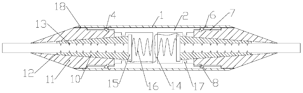
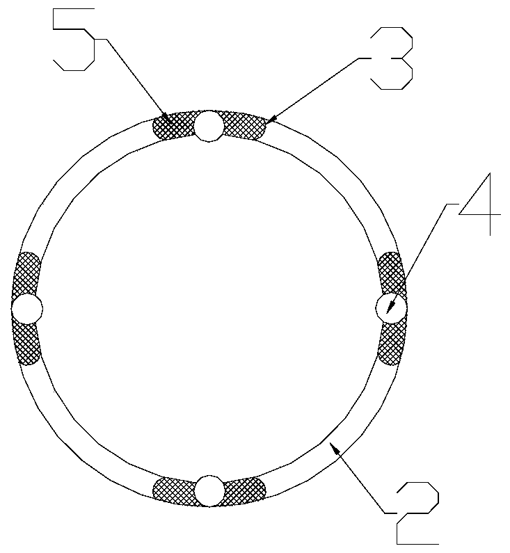
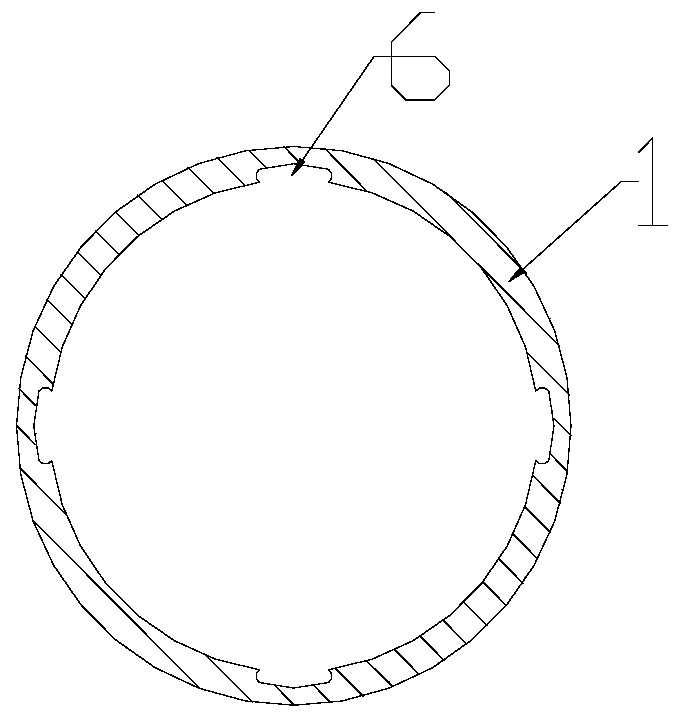
[0028] Such as Figure 1-5 As shown, a wire splicing device includes a conductive connection mechanism. Both ends of the conductive connection mechanism are plugged with wire joints. The conductive connection mechanism includes an outer shell 1 and an inner insulating sleeve 2 threaded on the inner side of the outer shell 1. The inner insulating sleeve 2 There is a conductive component electrically connected to the wire joint inside, the end of the inner insulating sleeve 2 is provided with strip-shaped sliding holes 3 at intervals along the circumferential direction, and a damping ball 4 is slid inside the strip-shaped sliding hole 3, and the inside of the strip-shaped sliding hole 3 The inner diameter is smaller than the diameter of the damping ball 4, and the outer diameter is larger than the diameter of the damping ball 4. The strip-shaped sliding holes 3 on both sides of the damping ball 4 are filled with damping rubber 5. The storage groove 6 for accommodating the dampin...

Embodiment 2

[0033] This embodiment is basically the same as Embodiment 1, the difference is: as Figure 5-6 As shown, the wire joint includes two semicircular tapered conductive sleeves 10 and a wire insulating sleeve 11 set on the outside of the tapered conductive sleeve 10. The inner side of the wire insulating sleeve 11 is provided with a tapered hole that matches the tapered guide sleeve. 12. The inner wall of the conical conductive sleeve 10 is fixed with a piercing contact 13 electrically connected to the wire. One end of the tapered conductive sleeve 10 with a smaller diameter is placed in the tapered hole 12 , and the end with a larger diameter extends out of the tapered hole 12 . Through the cooperation of the tapered hole 12 and the tapered conductive sleeve 10, the tapered conductive sleeve 10 is always pressed against the wire to prevent the wire from falling off, and at the same time avoid the separation of the tapered conductive sleeve 10 and the wire insulating sleeve 11; p...

Embodiment 3

[0041] This embodiment is basically the same as embodiment one or two, the difference is: as Figure 7 and 8 As shown, between the outer shell 1 and the inner insulating sleeve 2 there is a positioning assembly which restricts the rotation of the outer shell 1 evenly in the circumferential direction. The positioning assembly includes a positioning groove 19 arranged on the outer wall of the inner insulating sleeve 2. Telescopic groove 20, the limit block 21 is slidingly arranged in the telescopic groove 20, the limit block 21 is connected with the inner wall of the telescopic groove 20 by the first compression spring 22, the housing 1 is equipped with a positioning rod 23, and the lower end of the positioning rod 23 is provided with a The lower arc-shaped tip 24 is integrally formed with the positioning rod 23 and is placed at the lower end of the limiting block 21 . The side wall of the positioning rod 23 is provided with a slot 25 that cooperates with the limiting block 21 ....


PUM


Abstract

The invention provides a wire connection device and a using method thereof. The device comprises a conductive connection mechanism. Two ends of the conductive connection mechanism are plugged with wire joints; the conductive connection mechanism comprises a shell and an inner insulating sleeve in threaded connection with an inner side of the shell; a conductive assembly electrically connected withthe wire joints is arranged in the inner insulating sleeve; strip-shaped sliding holes are arranged in an end part of the inner insulating sleeve at intervals along a circumferential direction; damping balls are arranged in the strip-shaped sliding holes in a sliding manner; an inner diameter of each strip-shaped sliding hole is smaller than a diameter of each damping ball; an outer diameter is greater than the diameter of the damping ball; and the strip-shaped sliding holes in the two sides of each damping ball are filled with damping rubber, a containing groove used for containing the damping balls is arranged in the inner wall of the shell, an assembling groove is arranged in the outer side wall of each wire joint, a damping ring is arranged on the outer side wall of the assembling groove, and a limiting groove abutting against each damping ball is arranged in the side, away from an end portion of the wire, of the damping ring. Automatic locking of the wire joint and the conductiveconnecting mechanism is realized, a torsion acting force of the wire is weakened, and the wire is prevented from being broken by torsion.

Description

technical field [0001] The invention relates to the field of electric power technology, in particular to a wire connection device and a method for using the same. Background technique [0002] When the conductor length of the overhead transmission line is not enough, or the conductor is worn and broken, it is usually necessary to use a connecting device to connect the two conductors together. Due to the influence of weather conditions such as wind and snow, the wires are prone to fatigue vibrations in multiple directions, such as breeze vibration, ice-covered dancing, etc., which may easily cause wire breakage. However, the existing wire connection devices seldom consider the above problems, resulting in The wire at the connecting device is easy to wear and break again. In addition, to prevent the wire from breaking due to vibration, in addition to considering the vibration of the wire in multiple directions, it is also necessary to consider how to avoid stress concentration...

Claims


Application Information

Patent Timeline
Patent Type & Authority Applications(China)
IPC IPC(8): H01R11/01H01R11/09H01R4/48
CPCH01R4/4863H01R11/01H01R11/09
Inventor 李鹏飞路延伟李知雨陈曦辉黄凯钱红艳陈琳琳
Owner 国网河南省电力公司宝丰县供电公司
Why Eureka
Try Eureka