
Flat wire continuous wave winding, stator and motor

A wave winding and flat wire technology, applied in the field of motors, can solve problems such as production difficulties, flat wire motors with many solder joints, and easy damage

Pending Publication Date: 2020-07-24
NIO CO LTD
View PDF0 Cites 8 Cited by
  • Summary
  • Abstract
  • Description
  • Claims
  • Application Information

AI Technical Summary

Problems solved by technology

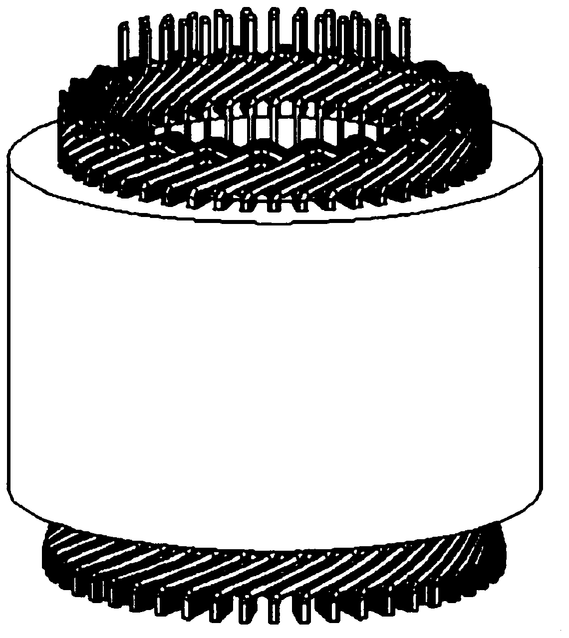
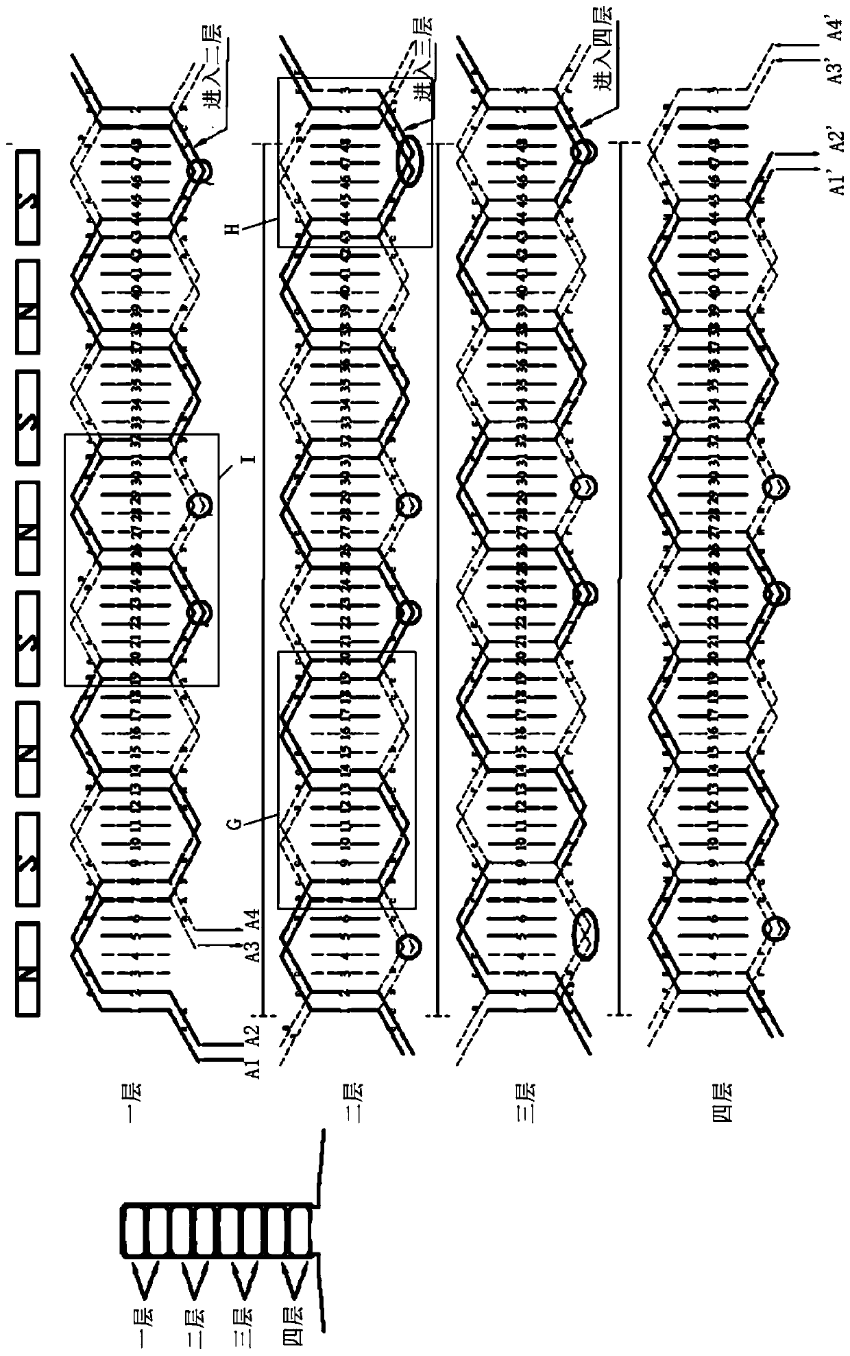
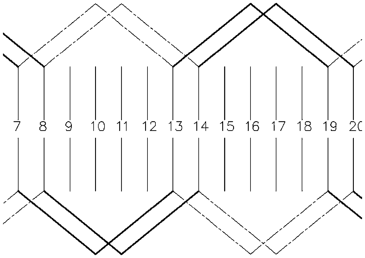
[0008] In order to solve the above problems in the prior art, that is, in order to solve the problem of difficult production and easy damage caused by the large number of solder joints of flat wire motors in the prior art, the present invention provides a flat wire continuous wave winding, which is characterized in that, The flat wire continuous wave winding includes an incoming wire end, an outgoing wire end, and an S-shaped wave winding between the incoming wire end and the outgoing wire end, and the number of winding layers of the flat wire continuous wave winding is 2N. The pitch is y, and the connection between the Nth layer and the N+1th layer of the flat wire continuous wave winding is provided with a jump winding part, and the pitch of each phase wire group at the jump winding part is y +1; where N and y are natural numbers greater than or equal to 1

Method used


Image

  • Flat wire continuous wave winding, stator and motor
  • Flat wire continuous wave winding, stator and motor
  • Flat wire continuous wave winding, stator and motor

Examples


Embodiment Construction

[0033] Preferred embodiments of the present invention are described below with reference to the accompanying drawings. Those skilled in the art should understand that these embodiments are only used to explain the technical principles of the present invention, and are not intended to limit the protection scope of the present invention. Those skilled in the art can make adjustments as needed so as to adapt to specific applications. For example, although it is described in the specification that the whole flat wire is wound continuously from the beginning to the end without solder joints as an example, the present invention can obviously use two shorter flat wires to be wound after welding. As long as the number of solder joints can be reduced compared with the prior art.

[0034] It should be noted that, in the description of the present invention, the terms "center", "upper", "lower", "left", "right", "vertical", "horizontal", "inner", "outer" etc. The terms of the indicated...


PUM


Abstract

The invention belongs to the technical field of test equipment, and particularly provides a flat wire continuous wave winding, a stator and a motor. The invention aims to solve the problems of difficult production and easy damage caused by many welding spots of a flat wire motor in the prior art. The flat wire continuous wave winding comprises a wire inlet end, a wire outlet end and an S-shaped wave winding located between the wire inlet end and the wire outlet end. The number of winding layers of the flat wire continuous wave winding is 2N, and the pitch is y. A jump winding part is arrangedat the joint of the Nth layer and the (N + 1) th layer of the flat wire continuous wave winding. The pitch of each phase of wire group at the jump winding part is y + 1, wherein N and y are both natural numbers greater than or equal to 1. According to the flat wire continuous wave winding, a scheme of continuously winding a flat wire is adopted, so that welding spots are reduced.

Description

technical field [0001] The invention belongs to the technical field of motors, and specifically provides a flat wire continuous wave winding, a stator and a motor. Background technique [0002] The main development trend of new energy vehicle motors is miniaturization and high speed, and miniaturization will inevitably require a significant increase in motor power density. From the perspective of technical requirements, the peak power density of new energy vehicle drive motors must reach 4kw / kg, while At present, this data has only reached 3.2-3.3kw / kg, so at least a 30% increase is needed. [0003] The difference between flat wire motors and round wire motors lies in the forming method of copper wires. Flat wires are conducive to the improvement of motor slot fill rate. Generally, the slot fill rate of round wire motors is about 40%, while the slot fill rate of flat wire motors can reach More than 60%. The improvement of the slot full rate means that more copper wires can...

Claims


Application Information

Patent Timeline
IPC IPC(8): H02K3/28H02K1/16
CPCH02K1/16H02K3/28
Inventor 兰红玉高海龙耿利敏
Owner NIO CO LTD
Learn More