Annular belt assembly line device

A ring-shaped, flowing water technology, applied in conveyor objects, conveyors, transportation and packaging, etc., can solve problems such as slow mechanical operation, falling, dust diffusion, etc., to increase sliding speed, increase stability, and avoid falling. Effect

Inactive Publication Date: 2020-07-28
唐本春
View PDF0 Cites 4 Cited by
  • Summary
  • Abstract
  • Description
  • Claims
  • Application Information

AI Technical Summary

Problems solved by technology

The usual belt conveyors are straight-line conveying, and some belt conveyors can be made into curved conveying, but the common endless belt conveying equipment is formed by a combination of straight-line conveying and curved conveying, and there are joints or multi-section direct conveying belt joints , there will be a problem of material leakage when conveying materials, and some waste generated during processing will fall into the mechanical gap, resulting in slow operation of the machine and diffusion of dust, causing environmental pollution

Method used


Image

  • Annular belt assembly line device
  • Annular belt assembly line device
  • Annular belt assembly line device

Examples


Embodiment 1

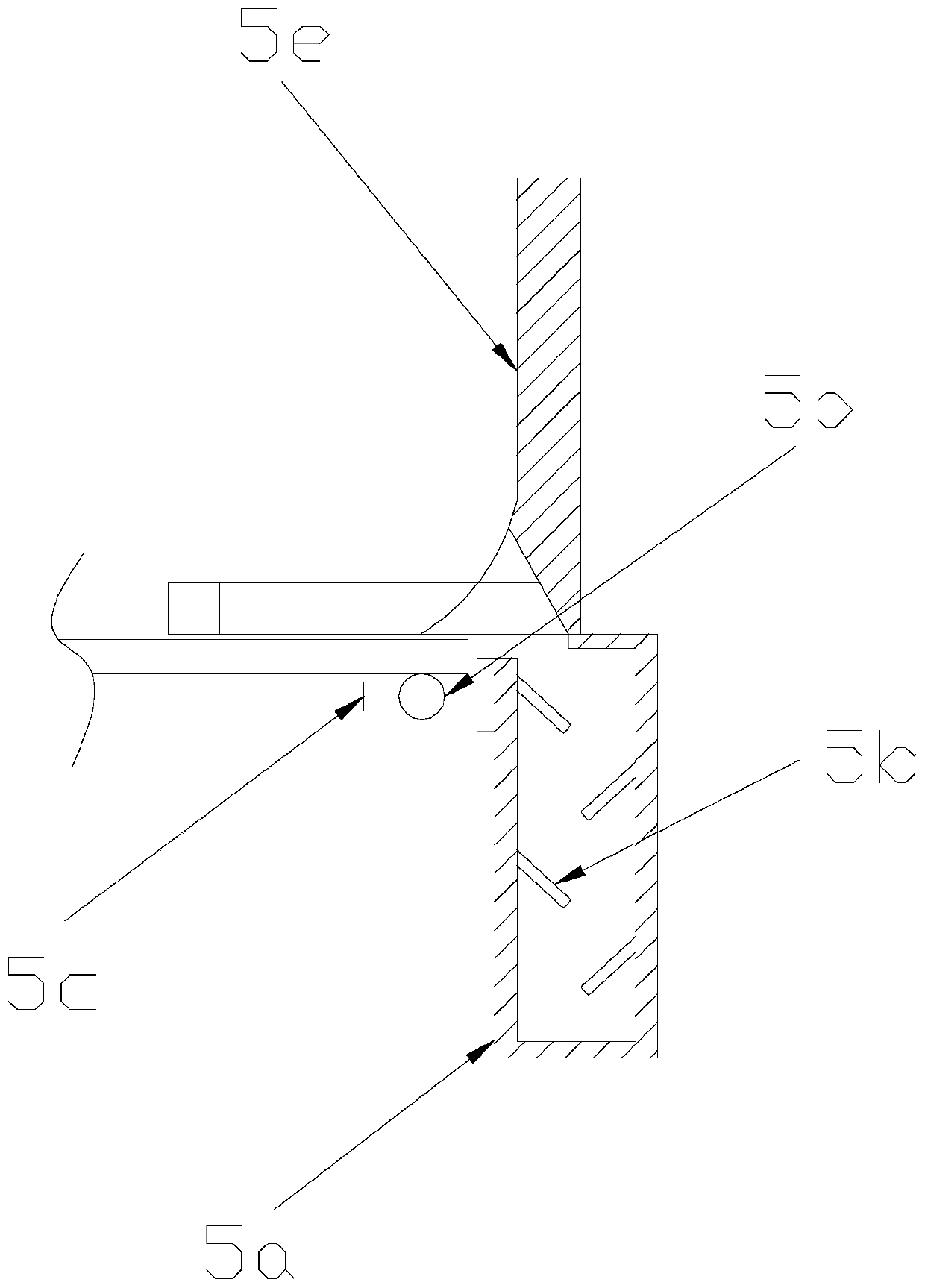
[0027] see Figure 1-Figure 6 , the present invention provides a ring-shaped belt flow equipment, the structure of which includes a linear conveyor 1, a conveyor belt 2, a curve conveyor 3, an electric controller 4, a chip collecting device 5, and a sliding mechanism 6. The linear conveyor The left and right ends of 1 are equipped with curved conveyors 3, the linear conveyor 1 and the curved conveyor 3 are movably connected by the sliding mechanism 6, and the two linear conveyors 1 and the two curved conveyors 3 form a ring structure, the electric controller 4 is provided under the curved conveyor 3, the curved conveyor 3 is connected to the electric controller 4, and the surface of the linear conveyor 1 and the curved conveyor 3 are equipped with transmission The belt 2, the surface of the linear conveyor 1 and the curved conveyor 3 are provided with a chip collecting device 5, and the linear conveyor 1 and the curved conveyor 3 are both movably connected with the chip collec...

Embodiment 2

[0034] see Figure 1-Figure 6 , the present invention provides a ring-shaped belt flowing water equipment, the described sliding aid mechanism 6 is composed of a second debris collecting box 6a, an anti-backflow mechanism 6b, a support ear 6c, a second rotating shaft 6d, and a sliding aiding guide roller 6e, the described Two pairs of support ears 6c are provided on the top of the second dust collection box 6a, the second dust collection box 6a and the support ears 6c are fixedly connected, and an anti-backflow mechanism 6b is installed inside the second dust collection box 6a, The left and right ends of the sliding guide roller 6e are provided with a second rotating shaft 6d, the sliding guiding roller 6e and the second rotating shaft 6d are welded by electric welding, and the supporting ear 6c is provided with a sliding guiding roller 6e , the support ear 6c and the sliding guide roller 6e adopt clearance fit through the second rotating shaft 6d.

[0035] The anti-backflow ...


PUM


Abstract

The invention discloses an annular belt assembly line device. The annular belt assembly line device structurally comprises a linear conveyor, a conveying belt, a turning conveyor, an electric controller, a scrap collecting device and a sliding assisting mechanism, wherein the scrap collecting device is composed of a first scrap collecting box, an inclined plate, a belt binding plate, balls and a protection plate. An annular belt assembly line is formed by combining the linear conveyor and the turning conveyor in pairs, during conveying, the scrap collecting device is used for collecting scrapsinto the first scrap collecting box concentratedly, and the edge lines of the conveying belt are supported through the belt binding plate, so that the edge of the conveying belt is not damaged by friction with the inner wall of a machine, the protection plate uses a material bouncing rod to intercept and rebound materials deviating from the original position, and the conveying stability is improved; and a joint gap between the linear conveyor and the turning conveyor passes through the sliding assisting mechanism, so that the sliding speed of the materials can be increased by means of slidingassisting guide rollers when the materials are conveyed, the materials are prevented from falling off, and the deviation situation of the materials during conveying is avoided through the design.

Description

technical field [0001] The invention relates to the field of belt assembly lines, in particular to an endless belt assembly line. Background technique [0002] Industrial production technology is constantly improving, and the requirements for automation are getting higher and higher. The manual production methods in traditional industrial production can no longer meet the needs of modernization. Belt conveyor is a common equipment in automatic production, which can transport various materials. The usual belt conveyors are straight-line conveying, and some belt conveyors can be made into curved conveying, but the common endless belt conveying equipment is formed by a combination of straight-line conveying and curved conveying, and there are joints or multi-section direct conveying belt joints , There will be a problem of material leakage when conveying materials, and some waste generated during processing will fall into the mechanical gap, resulting in slow operation of the ...

Claims


Application Information

Patent Timeline
Patent Type & Authority Applications(China)
IPC IPC(8): B65G15/00B65G15/58B65G41/00
CPCB65G15/00B65G15/58B65G41/00
Inventor 唐本春
Owner 唐本春
Why Eureka
Try Eureka